Arduino Nano + M5451B7
- Войдите на сайт для отправки комментариев
Вс, 02/12/2018 - 10:54
Всем привет!
Не удается завести связку Arduino Nano + M5451B7. С питанием всё нормально, проверил. Скачал библиотеку:
https://code.google.com/archive/p/arduino-m5451-current-driver/
подключил согласно wiki:
https://code.google.com/archive/p/arduino-m5451-current-driver/wikis/Ard...
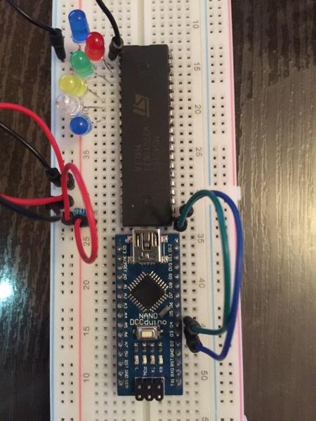
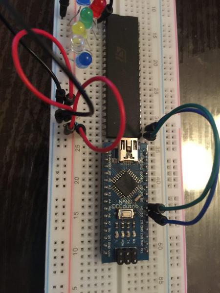
Залил в нанл скетч из примера (begin_here) ничего не меняя, но светодиоды не загораются, точнее они загоряются, если я вытащу один из проводов (DATA или CLOCK) а не по алгоритму. Я подключил DATA И CLOCK на 3 и 4 цифровые выходы arduino, но не знаю, надо ли и где если надо указывать эти PINы в скетче. Спасибо.
где вы эту дичь нашли - 48 Мб кода ради одного токового шунта???
Кодна нет, библиотеки нет. Чего Вы ждёте?
Приведите скетч и код библиотеки. Или уж прямую ссылку на код библтиотеки. а не на чертё что, где ещё искать надо.
Ссылка на библиотеку: https://storage.googleapis.com/google-code-archive-downloads/v2/code.google.com/arduino-m5451-current-driver/lightuino5.1.6.zip
Скетч:
/*? <section name="examples"> <sketch name="begin_here"> This sketch shows basic Lightuino control, so you can get up and running quickly! <verbatim> */ // Include the appropriate Lightuino library #include <lightuino5.h> // If you have a shield, include L4 instead //#include <lightuino4.h> // These "print" wrappers just output to BOTH USB and UART serial ports (code at the bottom) void println(char*s); void print(char*s); void print(int i,char format=DEC); void println(int i,char format=DEC); // Standard Arduino "setup" function void setup(void) { // Start up the serial port. This is not required for the lightuino, I'm just doing it so I can print stuff. Serial.begin(9600); Serial.println("serial initialized"); // Start up the Lightuino's USB serial port. #ifdef Lightuino_USB // This #ifdef,#endif wrapper means the the code inside will only compile if your Lightuino has a USB port. // That way this sketch will work with multiple versions of the circuitboard. // But since you probably don't care that your sketch does so, you can leave these lines out. Usb.begin(); #endif // This line need to be removed if #ifdef is removed too! // Say hi so we know its working! println("Lightuino 4/5 Introduction Sketch V5.0"); } // Create the basic Lightuino 70 LED sink controller (the pins in the 2 40-pin IDE connectors) LightuinoSink sinks; // Create the Lightuino 16 channel source driver controller (the 16 pin connector) LightuinoSourceDriver sources; // This object PWMs the Lightuino sinks allowing individual LED brightness control, and provides array-based access to the Leds FlickerBrightness pwm(sinks); //?? Printf-style to the USB void p(char *fmt, ... ) { char tmp[128]; // resulting string limited to 128 chars va_list args; va_start (args, fmt ); vsnprintf(tmp, 128, fmt, args); va_end (args); Usb.print(tmp); } //?? A wrapper around delay so you can tweak how long the delays actually are... /* Do a delay, but also wait for user input if a global var is set */ char waitInput=false; boolean mydelay(int amt) { char incomingByte =0; delay(amt); if (waitInput) { // Wait for input from serial or usb serial while ((Serial.available()==0) #ifdef Lightuino_USB && (Usb.available()==0) #endif ) delay(10); } if (Serial.available()) incomingByte = Serial.read(); #ifdef Lightuino_USB else if (Usb.available()) incomingByte = Usb.read(); #endif if (incomingByte == 's') { println("stop"); waitInput=true; } else if (incomingByte == 'c') { println("continue"); waitInput=false; } else if (incomingByte == 'n') { println("next animation"); return false; } return true; } void mydelay_old(int amt) { delay(amt); } //?? This function demonstrates turning the 70 sinks on/off. The Lightuino can turn LEDs ON or OFF and not use any additional CPU. // To implement dimming requires the PWM (Pulse Width Modulation -- google it) technique, which is shown in the SinkPwmDemo // function below. Since both techniques are using the same LEDs, they can't be used at the same time. Instead use the PWM // technique only and set the LED intensity to off (0) or full (Lightuino_MAX_BRIGHTNESS-1). void SinkOnOffDemo() { println("Sink Discrete (On/OFF) Control Demo"); println(" Turn them all on!"); sinks.set(0xffffffff,0xffffffff,B00111111); // Each bit in these 3 numbers corresponds to one LED light mydelay(4000); println(" Turn on sequentially"); sinks.set(0,0,0); unsigned long int a=0,b=0; unsigned char c=0; for (int i=0;i<70;i++) // Instead of 70 you can use the constant "Lightuino_NUM_SINKS" { p("index %d\n",i); setbit(i,&a,&b,&c); // Set a particular bit in the a,b,c variables sinks.set(a,b,c); // Set the LEDs to be on/off based on these bits. mydelay(100); // Wait clearbit(i,&a,&b,&c); // Set a particular bit in the a,b,c variables to 0 mydelay(1); } if (0) for (int i=0;i<Lightuino_NUM_SINKS;i++) { clearbit(i,&a,&b,&c); // Set a particular bit in the a,b,c variables to 0 sinks.set(a,b,c); mydelay(100); } if (0) for (int i=0;i<5;i++) { println(" Turn on every other LED"); // Each bit (1 or 0) in this array corresponds to one LED light byte ledState[9] = {B10101010,B10101010,B10101010,B10101010,B10101010,B10101010,B10101010,B10101010,B10101010}; // Now send it to the chips. sinks.set(ledState); mydelay(250); println(" Now put in the opposite pattern"); // Now set up another pattern for (int j=0;j<9;j++) ledState[j] = B01010101; // Now send it to the chips. sinks.set(ledState); mydelay(250); } println(" Turn them all off!"); sinks.set(0,0,0); // Its THAT simple! // But before you go off and reinvent the wheel on top of the functions shown here, please check // out the more advanced animation functions used in the other sketches (for example lightuino_animations). // Mastering them will will let you code complex patterns with less effort than doing it yourself. } //?? Turn all the LEDs and source drivers off void AllOff(void) { sources.set(0); sinks.set(0,0,0); } //?? Turn all the LEDs and source drivers off void AllOn(void) { sources.set(0xffff); sinks.set(0xffffffff,0xffffffff,0xff); } //?? This function demonstrates PWM control over the LED sinks void SinkPwmDemo() { println("Now show brightness changes (PWM control)"); sinks.setBrightness(255); // Start PWMing automatically at around 4000hz. Generally you'd do this at the beginning of your sketch and leave it on the entire time, not at the beginning of a function. pwm.StartAutoLoop(4000); //pwm.brightness[35] = Lightuino_MAX_BRIGHTNESS-1; // mydelay(2000); for (int i=0;i<70;i++) { p("PWM index %d\n",i); pwm.brightness[i] = Lightuino_MAX_BRIGHTNESS-1; mydelay(250); pwm.brightness[i] = 0; mydelay(1); } if (0) for (int j=0;j<600;j++) { // You just set leds.brightness[LED_NUMBER] to the desired intensity (0 to LIGHTUINO_MAXBRIGHTNESS-1). // Note that you will see blinking at low intensities, so the minimum brightness you can set is around 30 // Here I will set each LED to a slightly different intensity. for (int i=0;i<70;i++) pwm.brightness[i] = (((i*3)+j)*100)%Lightuino_MAX_BRIGHTNESS; // Your homework is to figure out why this formula works! :-) // The CPU controls the rapid blinking that creates the variable brightness effect // so you must call leds.loop() rapidly to make it happen. // Note: You can also set it up so that the Lightuino library calls this function periodically automatically // by calling StartAutoLoop, which is what we have done above. //for (int i=0;i<400;i++) pwm.loop(); delay(10); // Because I am using "auto loop" I can do a normal "delay" and pwm.loop will be called in the background. } // All done! So turn off all the LEDs for (int i=0;i<70;i++) pwm.brightness[i] = 0; pwm.StopAutoLoop(); pwm.loop(); // Do it once more to turn off all LEDs. You have to do this manually because the autoloop might not have been called since all brightnesses were set to 0 } //?? This function demonstrates control over the source drivers (the 16 pin header on top) void SourceDriverDemo() { // clk,data,strobe,enable println("Source Driver Demo"); #if 0 println("Source 1"); sources.set(B1); mydelay(500); println("Source 2"); sources.set(B10); mydelay(500); println("Source 3"); sources.set(B100); mydelay(500); #endif println(" Driving alternating patterns"); if(1) for (int i=0;i<10;i++) { println(" 5"); sources.set(0x5555); mydelay(250); println(" a"); sources.set(0xaaaa); mydelay(250); } println(" Shifting 1 set bit (per 16 bits) through the chips."); sources.set(0x0000); for (int i=0;i<25;i++) { mydelay(250); sources.shift(((i&15)==0)); } sources.set(0); // All done, so turn them all off } void LightSensorDemo(void) { LightSensor light; // Initialize the light sensor // LightSensor light(5); // Note for shields: pass the analog line that the sensor is connected to. println("Light sensor demo"); print(" Current: "); int curval = light.read(); // Read it -- returns an "analog" number just like analogRead() (i.e. 0-1024) println(curval); println(" Cover the sensor fully to end the demo (automatically ends in 50 seconds)"); int val; int cnt = 0; do { val = light.read(); print(" Sensor value is: "); println(val); mydelay(300); cnt++; } while (cnt<50 && val<LightSensor::Dusk); // Some convenient constants are defined like "Dusk". See the header file or docs... } void IrDemo(void) { IrReceiver ir; // Initialize the IR receiver println("Infrared Receiver Demo"); println(" Waiting for input from your infrared remote -- demo will stop after 5 one-second intervals without input."); for (int i=0;i<500;) { unsigned long int code = ir.read(); // Read a code from the input buffer if (code) // Nonzero means a code was received. { // Print it out in hex and binary notation print(" code: "); print((unsigned long int)(code>>32),HEX); print(" "); print((unsigned long int)(code),HEX); print(" | "); print((unsigned long int)(code>>32),BIN); print(" "); println((unsigned long int)(code),BIN); i=0; } else // A zero means no code was received. { delay(10); i++; } } } const char* stringA = "LIGHTUINO 3 SEVENTY BY SIXTEEN LED MATRIX"; const char* stringB = "SALE TOILET PAPER LIGHTLY USED REROLLED"; void MatrixDemo(LightuinoSink& sink) { println("LED Matrix Demo"); // Create the matrix object. Pass the source and sink objects, the start scan line, and the total # of lines. In this case I am doing ALL of them. LightuinoMatrix mtx(sink,sources,0,16); println(" Turn on the entire matrix"); mtx.clear(1); // You've got to keep calling loop to paint each scan line in the matrix for (int j=0;j<5000;j++) { mtx.loop();} println(" Write a bit pattern into the entire matrix"); memset(mtx.videoRam,0xAA,((Lightuino_NUMOUTS/8)+1)*Lightuino_NUMSRCDRVR); // You've got to keep calling loop to paint each scan line in the matrix for (int j=0;j<5000;j++) { mtx.loop();} println(" Turn off the entire matrix"); mtx.clear(0); println(" Write Pixels"); for(int x=0;x<Lightuino_NUMOUTS;x++) { for(int y=0;y<Lightuino_NUMSRCDRVR;y++) { mtx.pixel(x,y,1); for (int j=0;j<10;j++) { mtx.loop();} } } mtx.clear(0); println(" Letter Marquee"); unsigned int cnt = 0; while(1) { cnt++; //if ((cnt & 511)==0) memset(mtx.videoRam,0xff,((Lightuino_NUMOUTS/8)+1)*Lightuino_NUMSRCDRVR); // Print some text to the matrix // the api is print(x,y,string,LetterSpacing,Operation) // The "fancy" math just shifts the letters by one pixel for every cnt, and then after // the width of a letter it resets the pixel shift and moves forward one character in the string mtx.print(0-(cnt%6),0,stringA+((cnt/6)%strlen(stringA)),1,DRAW); mtx.print(0-(cnt%6),8,stringB+((cnt/6)%strlen(stringB)),1,DRAW); for (int j=0;j<400;j++) { mtx.loop();} // Erase that same text mtx.print(0-(cnt%6),0,stringB+((cnt/6)%strlen(stringB)),1,ERASE); mtx.print(0-(cnt%6),8,stringA+((cnt/6)%strlen(stringA)),1,ERASE); } } void loop(void) { AllOn(); delay(100); AllOff(); // When the board boots up there will be random values in various chips resulting in some lights being on. So its good to turn everything off right away. //#if 0 SourceDriverDemo(); SinkOnOffDemo(); SinkPwmDemo(); //MatrixDemo(sinks); //#endif LightSensorDemo(); IrDemo(); } // This is a convenient function which illuminates the first and last LED on each side // so you can find the pins on the board. This sketch does not actually call this function, // its just here for your use. void pinFinder(void) { while (1) { pwm.brightness[0] = 32; pwm.brightness[34] = 64; pwm.brightness[35] = 128; pwm.brightness[69] = 255; for (int i=0;i<10;i++) pwm.loop(); } } // These "print" wrappers just output to BOTH serial ports // but you probably just want to use the Usb serial... void println(char*s) { Serial.println(s); #ifdef Lightuino_USB Usb.println(s); #endif } void print(char*s) { Serial.print(s); #ifdef Lightuino_USB Usb.print(s); #endif } void print(int i,char format) { Serial.print(i,format); #ifdef Lightuino_USB Usb.print(i,format); #endif } void println(int i,char format) { Serial.println(i,format); #ifdef Lightuino_USB Usb.println(i,format); #endif } /*? </verbatim></sketch></section> */#include <lightuino5.h>
Там определяются пины. И совсем не так, как Вы подключили. Поправьте.
да, это я видел,но не смог понять какой из них какой, например то же DATA left и right какой из них? или clock: