проверка модуля GY-91 10dof
- Войдите на сайт для отправки комментариев
Добрый день!
Использую ATmega32u4, определяющийся как Arduino Leondardo.
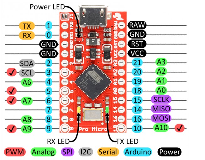
Скачал библиотеку "Adafruit_BMP280_Library-master", из нее взял пример скетча, скомпилировал, подключил по SPI: VIN-VCC, GND-GND, SCL-15(SCLK), SDA-16 (MOSI), SDO/SAO-14(MISO), CSB-10(A10) залил в ардуину, открыл "Монитор порта", двигаю модуль GY-91 в пространстве - нет сообщений в Мониторе порта, хотя должны быть согласно скетчу.
#include <Wire.h>
#include <SPI.h>
#include <Adafruit_Sensor.h>
#include <Adafruit_BMP280.h>

#define BMP_SCK 13
#define BMP_MISO 14
#define BMP_MOSI 16
#define BMP_CS 10

Adafruit_BMP280 bmp; // I2C
//Adafruit_BMP280 bmp(BMP_CS); // hardware SPI
//Adafruit_BMP280 bmp(BMP_CS, BMP_MOSI, BMP_MISO,  BMP_SCK);

void setup() {
  Serial.begin(9600);
  Serial.println(F("BMP280 test"));

  if (!bmp.begin()) {
    Serial.println(F("Could not find a valid BMP280 sensor, check wiring!"));
    while (1);
  }
}

void loop() {
    Serial.print(F("Temperature = "));
    Serial.print(bmp.readTemperature());
    Serial.println(" *C");

    Serial.print(F("Pressure = "));
    Serial.print(bmp.readPressure());
    Serial.println(" Pa");

    Serial.print(F("Approx altitude = "));
    Serial.print(bmp.readAltitude(1013.25)); // this should be adjusted to your local forcase
    Serial.println(" m");

    Serial.println();
    delay(2000);
}
Скачал библиотеку "MPU9250-master", из нее взял пример скетча, докачал библиотеку содержащую I2Cdev.h (требовалось при компиляции скетча), скомпилировал, подключил к нему модуль GY-91 по I2C (по крайней мере я так думаю), соединив: VIN-VCC, GND-GND, SCL-3 (SCL по скрину), SDA-2 (SDA по скрину), залил в ардуину, открыл "Монитор порта"- в "Монитор порта" идут строчки "0 0 0 0 0 0 ", периодически загорается светодиод. Двигаю модуль GY-91 в пространстве - не изменяются показания в Мониторе порта.
// I2C device class (I2Cdev) demonstration Arduino sketch for MPU9250
// 1/4/2013 original by Conor Forde <me@conorforde.com> at https://github.com/Snowda/MPU9250
//
// Changelog:
//     2014-03-27 - initial release

/* ============================================
I2Cdev device library code is placed under the MIT license

Permission is hereby granted, free of charge, to any person obtaining a copy
of this software and associated documentation files (the "Software"), to deal
in the Software without restriction, including without limitation the rights
to use, copy, modify, merge, publish, distribute, sublicense, and/or sell
copies of the Software, and to permit persons to whom the Software is
furnished to do so, subject to the following conditions:

The above copyright notice and this permission notice shall be included in
all copies or substantial portions of the Software.

THE SOFTWARE IS PROVIDED "AS IS", WITHOUT WARRANTY OF ANY KIND, EXPRESS OR
IMPLIED, INCLUDING BUT NOT LIMITED TO THE WARRANTIES OF MERCHANTABILITY,
FITNESS FOR A PARTICULAR PURPOSE AND NONINFRINGEMENT. IN NO EVENT SHALL THE
AUTHORS OR COPYRIGHT HOLDERS BE LIABLE FOR ANY CLAIM, DAMAGES OR OTHER
LIABILITY, WHETHER IN AN ACTION OF CONTRACT, TORT OR OTHERWISE, ARISING FROM,
OUT OF OR IN CONNECTION WITH THE SOFTWARE OR THE USE OR OTHER DEALINGS IN
THE SOFTWARE.
===============================================
*/

// Arduino Wire library is required if I2Cdev I2CDEV_ARDUINO_WIRE implementation
// is used in I2Cdev.h
#include "Wire.h"

// I2Cdev and MPU9150 must be installed as libraries, or else the .cpp/.h files
// for both classes must be in the include path of your project
#include "I2Cdev.h"
#include "MPU9250.h"

// class default I2C address is 0x68
// specific I2C addresses may be passed as a parameter here
// AD0 low = 0x68 (default for InvenSense evaluation board)
// AD0 high = 0x69
MPU9250 accelgyro;

int16_t ax, ay, az;
int16_t gx, gy, gz;
int16_t mx, my, mz;

#define LED_PIN 13
bool blinkState = false;

void setup() {
    // join I2C bus (I2Cdev library doesn't do this automatically)
    Wire.begin();

    // initialize serial communication
    // (38400 chosen because it works as well at 8MHz as it does at 16MHz, but
    // it's really up to you depending on your project)
    Serial.begin(19200);

    // initialize device
    Serial.println("Initializing I2C devices...");
    accelgyro.initialize();

    // verify connection
    Serial.println("Testing device connections...");
    Serial.println(accelgyro.testConnection() ? "MPU9250 connection successful" : "MPU9250 connection failed");

    // configure Arduino LED for
    pinMode(LED_PIN, OUTPUT);
}

void loop() {
    // read raw accel/gyro measurements from device
    accelgyro.getMotion9(&ax, &ay, &az, &gx, &gy, &gz, &mx, &my, &mz);

    // these methods (and a few others) are also available
    //accelgyro.getAcceleration(&ax, &ay, &az);
    //accelgyro.getRotation(&gx, &gy, &gz);

    // display tab-separated accel/gyro x/y/z values
    Serial.print("a/g/m:\t");
    Serial.print(ax); Serial.print("\t");
    Serial.print(ay); Serial.print("\t");
    Serial.print(az); Serial.print("\t");
    Serial.print(gx); Serial.print("\t");
    Serial.print(gy); Serial.print("\t");
    Serial.print(gz); Serial.print("\t");
    Serial.print(mx); Serial.print("\t");
    Serial.print(my); Serial.print("\t");
    Serial.println(mz);

    // blink LED to indicate activity
    blinkState = !blinkState;
    digitalWrite(LED_PIN, blinkState);
}
Подскажите что я делаю не так?

