Гироскоп зажигающий лед импульсами
- Войдите на сайт для отправки комментариев
Сб, 07/10/2017 - 18:35
всем привет, нужна помощь в реализации кода позволяющего зажигать лед диоды
Импульсами с заданной характеристикой. С привязкой героскопа 5060
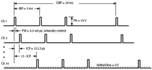
на выходе если все D pins обьединить в лед панель то должно получатся такой вот шлейфик по затухающей
Есть похожий скетч тут практически все реализованно
/**
 * Simple implementation false
 *
 * means that for  pitch/yaw there only be
 * a single led for each direction. The led will get more bright
 * as the direction increases
 *
 * Simple implementation true
 * means that for pitch/yaw there will be multiple led's that light up one by one
 *
 * The accelerometer/gyro is a MPU6050, it should be wired to the SDA and SCL pins
 */
#define SIMPLE_IMPLEMENTATION false

const int frontLed = 3;
const int bottomLed = 5;
const int rightLed = 6;
const int leftLed = 9;
long int lastPrintTime;

typedef struct
{
    byte pin;
    byte positionInsideGroup;
    char thePosition; // Left, Right, Up, Down
    byte minAngle;
    byte maxAngle;
} ledConfig;

ledConfig leds[] = {
    {3, 1, 'u', 31, 45},
    {12, 2, 'u', 16, 30},
    {11, 3, 'u', 5, 15},
    {5, 1, 'd', 5, 15},
    {6, 2, 'd', 16, 30},
    {7, 3, 'd', 31, 45},
    {8 , 1, 'r', 5, 23},
    {9, 2, 'r', 24, 45},
    {10, 1, 'l', 5, 23},
    {4, 2, 'l', 24, 45},
};

#include "I2Cdev.h"
#include "MPU6050_6Axis_MotionApps20.h"
#if I2CDEV_IMPLEMENTATION == I2CDEV_ARDUINO_WIRE
    #include "Wire.h"
#endif

MPU6050 mpu;

bool dmpReady = false;  // set true if DMP init was successful
uint8_t mpuIntStatus;   // holds actual interrupt status byte from MPU
uint8_t devStatus;      // return status after each device operation (0 = success, !0 = error)
uint16_t packetSize;    // expected DMP packet size (default is 42 bytes)
uint16_t fifoCount;     // count of all bytes currently in FIFO
uint8_t fifoBuffer[64]; // FIFO storage buffer

// orientation/motion vars
Quaternion q;           // [w, x, y, z]         quaternion container
VectorInt16 aa;         // [x, y, z]            accel sensor measurements
VectorInt16 aaReal;     // [x, y, z]            gravity-free accel sensor measurements
VectorInt16 aaWorld;    // [x, y, z]            world-frame accel sensor measurements
VectorFloat gravity;    // [x, y, z]            gravity vector
float euler[3];         // [psi, theta, phi]    Euler angle container
float ypr[3];           // [yaw, pitch, roll]   yaw/pitch/roll container and gravity vector
volatile bool mpuInterrupt = false;     // indicates whether MPU interrupt pin has gone high

void setup()
{
    #if I2CDEV_IMPLEMENTATION == I2CDEV_ARDUINO_WIRE
        Wire.begin();
        TWBR = 24; // 400kHz I2C clock (200kHz if CPU is 8MHz)
    #elif I2CDEV_IMPLEMENTATION == I2CDEV_BUILTIN_FASTWIRE
        Fastwire::setup(400, true);
    #endif

    Serial.begin(9600);
    while (!Serial); // wait for Leonardo enumeration, others continue immediately
    Serial.println(F("Initializing I2C devices..."));
    mpu.initialize();
    Serial.println(F("Testing device connections..."));
    Serial.println(mpu.testConnection() ? F("MPU6050 connection successful") : F("MPU6050 connection failed"));
    Serial.println(F("Initializing DMP..."));
    devStatus = mpu.dmpInitialize();
    mpu.setXGyroOffset(220);
    mpu.setYGyroOffset(76);
    mpu.setZGyroOffset(-85);
    mpu.setZAccelOffset(1788); // 1688 factory default for my test chip
    if (devStatus == 0) {
        // turn on the DMP, now that it's ready
        Serial.println(F("Enabling DMP..."));
        mpu.setDMPEnabled(true);
        Serial.println(F("Enabling interrupt detection (Arduino external interrupt 0)..."));
        attachInterrupt(0, dmpDataReady, RISING);
        mpuIntStatus = mpu.getIntStatus();
        Serial.println(F("DMP ready! Waiting for first interrupt..."));
        dmpReady = true;
        packetSize = mpu.dmpGetFIFOPacketSize();
    } else {
        Serial.print(F("DMP Initialization failed (code "));
        Serial.print(devStatus);
        Serial.println(F(")"));
    }
    if (SIMPLE_IMPLEMENTATION) {
        initializeLEDsSimple();
    } else {
        initializeLEDsMultiple();
    }
    lastPrintTime = millis();
}

void loop()
{
    if (!dmpReady) return;
    mpuInterrupt = false;
    mpuIntStatus = mpu.getIntStatus();
    fifoCount = mpu.getFIFOCount();
    if ((mpuIntStatus & 0x10) || fifoCount == 1024) {
        mpu.resetFIFO();
        Serial.println(F("FIFO overflow!"));
    } else if (mpuIntStatus & 0x02) {
        while (fifoCount < packetSize) {
          fifoCount = mpu.getFIFOCount();
        }
        mpu.getFIFOBytes(fifoBuffer, packetSize);
        fifoCount -= packetSize;
        mpu.dmpGetQuaternion(&q, fifoBuffer);
        mpu.dmpGetGravity(&gravity, &q);
        mpu.dmpGetYawPitchRoll(ypr, &q, &gravity);
        int x = ypr[0] * 180/M_PI;
        int y = ypr[1] * 180/M_PI;
        int z = ypr[2] * 180/M_PI;
        Serial.print(y);Serial.print("\t");Serial.println(z);
        if (SIMPLE_IMPLEMENTATION) {
            flashLEDsSimple(x, y, z);
        } else {
            flashLEDsMultiple(x, y, z);
        }
    }
}

void initializeLEDsSimple()
{
    pinMode(frontLed, OUTPUT);
    pinMode(bottomLed, OUTPUT);
    pinMode(rightLed, OUTPUT);
    pinMode(leftLed, OUTPUT);
}

void initializeLEDsMultiple()
{
    for (int i=0; i<10; i++) {
        Serial.println(leds[i].pin);
        pinMode(leds[i].pin, OUTPUT);
    }
    delay(3000);
}

void flashLEDsSimple(int x, int y, int z)
{
    if (y > 0) {
        analogWrite(rightLed, y*4);
        analogWrite(leftLed, 0);
    } else {
        analogWrite(leftLed, y*4*-1);
        analogWrite(rightLed, 0);
    }
    if (z > 0) {
        analogWrite(bottomLed, z*4);
        analogWrite(frontLed, 0);
    } else {
        analogWrite(frontLed, z*4*-1);
        analogWrite(bottomLed, 0);
    }
}

void flashLEDsMultiple(int x, int y, int z)
{
    for (int i=0; i<10; i++) {
        //Serial.print(z);Serial.print(",");Serial.print(leds[i].thePosition);Serial.print(",");Serial.println(leds[i].minAngle);
        bool modified = false;
        if (z < 0 && leds[i].thePosition == 'u' && abs(z) > leds[i].minAngle) {
            digitalWrite(leds[i].pin, HIGH);
            modified = true;
        }
        if (z > 0 && leds[i].thePosition == 'd' && abs(z) > leds[i].minAngle) {
            digitalWrite(leds[i].pin, HIGH);
            modified = true;
        }
        if (y < 0 && leds[i].thePosition == 'l' && abs(y) > leds[i].minAngle) {
            digitalWrite(leds[i].pin, HIGH);
            modified = true;
        }
        if (y > 0 && leds[i].thePosition == 'r' && abs(y) > leds[i].minAngle) {
            digitalWrite(leds[i].pin, HIGH);
            modified = true;
        }
        if (!modified) {
            digitalWrite(leds[i].pin, LOW);
        }
    }
}

void dmpDataReady()
{
    mpuInterrupt = true;
}
Однако надо допилить что бы на выходе били импульсы по схеме выше и задействовать все пины ардуины (последнее не кспеху) что бы можно было в панель обьединить выходы.
Примерный код импульсов я даже нашел как бы это теперь в одно совместить
Однако тут не учтены интервалы между импульсами
int led = 3; // the pin that the LED is attached to int brightness = 0; // how bright the LED is int fadeAmount = 10; // how many points to fade the LED by // the setup routine runs once when you press reset: void setup() { // declare pin 3 to be an output: pinMode(led, OUTPUT); } // the loop routine runs over and over again forever: void loop() { // set the brightness of pin 3: analogWrite(led, brightness); // change the brightness for next time through the loop: brightness = brightness + fadeAmount; // reverse the direction of the fading at the ends of the fade: if (brightness == 0 || brightness == 255) { fadeAmount = -fadeAmount ; } // wait for 30 milliseconds to see the dimming effect delay(30); }Т.е. вам нужен analogWrite() на всех выводы ардуины, а не только на 6 стандартных?
Идея очень проста нужно создать панельку из лед диодов примерно такую.
И в зависимости от поворота гироскопа назад верх лево право.
Должны зажигатся светодиоды с fade эффектом по затухающей (главное что бы там были импульсы).
Вот и думаю как это сделать увы но с програмированием туго у меня :(
на видео реализация кода что выше
https://youtu.be/lYH1H_nWLz4
однако тут лево и право токо по 2 диода а надо бы по 3 со всех сторон. (назад верх лево право.)
Ну да это это мелочи, самое главное запилить fade эффект на зажигание светодиодов.
И понятное дело что время фейд эффекта должно быть минимальным эначе при изменении положения героскопа будет залипание показаний
можно реализовать любую зависимость при использовании адресных светодиодов, хоть сто . Пришлите точное задание с описанием зависимости от выхода 6050 по адресу ydom@mail.ru
Адресуемых. Дороже, но реальней. На обычных нет шансов с обычной ардуиной, имхо.