Библиотека под такой протокол
- Войдите на сайт для отправки комментариев
Сб, 17/06/2017 - 20:07

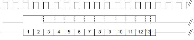
Для работы АЦП на него надо подавать тактовый сигнал (строка 1 на рисунке), стартовый бит (строка 2) и АЦП будет выдавать 13 бит последовательным кодом (строка 3). Стартовый бит можно подавать в формате "длинный" или "короткий" - соответсвенно рисунки 2 и 1.
Есть ли готовая библиотека под такой протокол, чтобы не изобретать велосипед?
короткий старт-бит:
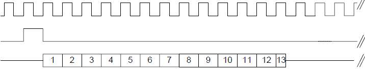
длинный старт-бит:
А чем SPI не подходит? Хоть программная, хоть аппаратная. Верхняя это CLK, средняя это CS,Немного корректировать а нижняя это MISO.
Можно еще веселее средний MOSI взять . Итого CLK/MOSI/MISO . Отправил по MOSI как бы длиный/короткий строб и MISO Заглотнул 2 байта . В Ардуино библиотека SPI.h
Я только начинаю, не судите пожалуйста строго.
Доступна функция отправки 1 байт (8 бит). А мне нужно 1 бит или 14 бит (длинный режим= 13+ 1 стартовый). Как это сделать ? https://www.arduino.cc/en/Reference/SPI http://arduino.ru/Reference/Library/SPI
И как одна функция transfer() http://arduino.ru/Reference/Library/SPI/transfer может использоваться одновременно на чтение и запись?
Понятно, что master передает по MOSI и slave по MISO. Хочу понять глубже - если бы сопряженное устройство было бы двунаправленным , то невольно придется передавать ему байт ради приема байта.
Устройство может трактовать переданный ему байт как управляющую команду, что хорошего выйдет из этого ?
CS - это выбор устройства.
К одним и тем же MOSI, MISO и CLK можно подключить несколько разных устройств. С каким из них общаться, определяет как раз сигнал CS - на выбранном устройстве он низкий, а на всех остальных - высокий.
Если число байт для передачи некратно 8, нужно округлять в большую сторону.
SPI - полнодуплексный протокол. Соответственно, передача одновременно идет в обе стороны.
Ну для АЦП как раз сначала ему передается команда (адрес), и только после этого с него можно получить данные.
У вас 14 бит . Вот и передавайте их двумя посылками по 8 байт. Лишним битам дайте 0. И обратно прием двух посылок по 8 бит. Лишние вы просто игнорируете. SPI это регистр последовательного сдвига , один бит передается и одновременно один бит принимается. 8 тактов идет считавание информации с этого регистра, и потом запись.
В SPI 2 посылки по1 байту это 16 бит без пауз между ними, те 16 тактов, а не 17++++++++ ?
Power up input (PUI) signal. When this pin is tied to VDD, the part is powered up. When tied to VSS,
the part is powered down.
Another way to power down is to set the PUI pin to LOW. When the system needs to be powered up again, the PUI pin needs to be set to HIGH and the Frame Sync pulse needs to be present. It will take two Frame Sync cycles before the pin PCMT will become low impedance.
Если вы хотите потрепаться, то я не буду вам мешать . А если по делу. То CLK в SPI тактует только по делу. Нет посылок приема , то и нет тактов. Передача 8 байт (формировка вашего старт бита) - 8 импульсов, прием байта 8 импульсов, прием еще байта - еще 8 импульсов. Так что хотите лишние испульсы - отправляйте или принимайте в холостую.
Я о другом. Если подряд без задержки послать функцией transfer() в SPI байт 0xFF, а за ним еще один байт 0b11111000, то на линии MOSI будет 13 битов HIGH и 5 битов LOW или на границе между байтами может получиться разрыв в 1 или более тактов ?
Если разрыв, то и SCLK как Вы написали в это время не будет работать и сорвется незаконченный прием из АЦП?
Ничего хорошего пока не получилось, послал 2 байта 0xFF и 0xFF, на выводе MOSI при помощи двух прерываний подсчитал что получается : 2 передних фронта (RISING) импульсов и 2 задних (FALLING). А мне нужно 1 передний и 1 задний фронт.
Как убрать "иголку" между импульсами?
Идем по пути "C:\Program Files (x86)\Arduino\hardware\arduino\avr\libraries\SPI\src\SPI.h"
Открываем файл SPI.h
/*
 * Copyright (c) 2010 by Cristian Maglie <c.maglie@arduino.cc>
 * Copyright (c) 2014 by Paul Stoffregen <paul@pjrc.com> (Transaction API)
 * Copyright (c) 2014 by Matthijs Kooijman <matthijs@stdin.nl> (SPISettings AVR)
 * Copyright (c) 2014 by Andrew J. Kroll <xxxajk@gmail.com> (atomicity fixes)
 * SPI Master library for arduino.
 *
 * This file is free software; you can redistribute it and/or modify
 * it under the terms of either the GNU General Public License version 2
 * or the GNU Lesser General Public License version 2.1, both as
 * published by the Free Software Foundation.
 */

#ifndef _SPI_H_INCLUDED
#define _SPI_H_INCLUDED

#include <Arduino.h>

// SPI_HAS_TRANSACTION means SPI has beginTransaction(), endTransaction(),
// usingInterrupt(), and SPISetting(clock, bitOrder, dataMode)
#define SPI_HAS_TRANSACTION 1

// SPI_HAS_NOTUSINGINTERRUPT means that SPI has notUsingInterrupt() method
#define SPI_HAS_NOTUSINGINTERRUPT 1

// SPI_ATOMIC_VERSION means that SPI has atomicity fixes and what version.
// This way when there is a bug fix you can check this define to alert users
// of your code if it uses better version of this library.
// This also implies everything that SPI_HAS_TRANSACTION as documented above is
// available too.
#define SPI_ATOMIC_VERSION 1

// Uncomment this line to add detection of mismatched begin/end transactions.
// A mismatch occurs if other libraries fail to use SPI.endTransaction() for
// each SPI.beginTransaction().  Connect an LED to this pin.  The LED will turn
// on if any mismatch is ever detected.
//#define SPI_TRANSACTION_MISMATCH_LED 5

#ifndef LSBFIRST
#define LSBFIRST 0
#endif
#ifndef MSBFIRST
#define MSBFIRST 1
#endif

#define SPI_CLOCK_DIV4 0x00
#define SPI_CLOCK_DIV16 0x01
#define SPI_CLOCK_DIV64 0x02
#define SPI_CLOCK_DIV128 0x03
#define SPI_CLOCK_DIV2 0x04
#define SPI_CLOCK_DIV8 0x05
#define SPI_CLOCK_DIV32 0x06

#define SPI_MODE0 0x00
#define SPI_MODE1 0x04
#define SPI_MODE2 0x08
#define SPI_MODE3 0x0C

#define SPI_MODE_MASK 0x0C  // CPOL = bit 3, CPHA = bit 2 on SPCR
#define SPI_CLOCK_MASK 0x03  // SPR1 = bit 1, SPR0 = bit 0 on SPCR
#define SPI_2XCLOCK_MASK 0x01  // SPI2X = bit 0 on SPSR

// define SPI_AVR_EIMSK for AVR boards with external interrupt pins
#if defined(EIMSK)
  #define SPI_AVR_EIMSK  EIMSK
#elif defined(GICR)
  #define SPI_AVR_EIMSK  GICR
#elif defined(GIMSK)
  #define SPI_AVR_EIMSK  GIMSK
#endif

class SPISettings {
public:
  SPISettings(uint32_t clock, uint8_t bitOrder, uint8_t dataMode) {
    if (__builtin_constant_p(clock)) {
      init_AlwaysInline(clock, bitOrder, dataMode);
    } else {
      init_MightInline(clock, bitOrder, dataMode);
    }
  }
  SPISettings() {
    init_AlwaysInline(4000000, MSBFIRST, SPI_MODE0);
  }
private:
  void init_MightInline(uint32_t clock, uint8_t bitOrder, uint8_t dataMode) {
    init_AlwaysInline(clock, bitOrder, dataMode);
  }
  void init_AlwaysInline(uint32_t clock, uint8_t bitOrder, uint8_t dataMode)
    __attribute__((__always_inline__)) {
    // Clock settings are defined as follows. Note that this shows SPI2X
    // inverted, so the bits form increasing numbers. Also note that
    // fosc/64 appears twice
    // SPR1 SPR0 ~SPI2X Freq
    //   0    0     0   fosc/2
    //   0    0     1   fosc/4
    //   0    1     0   fosc/8
    //   0    1     1   fosc/16
    //   1    0     0   fosc/32
    //   1    0     1   fosc/64
    //   1    1     0   fosc/64
    //   1    1     1   fosc/128

    // We find the fastest clock that is less than or equal to the
    // given clock rate. The clock divider that results in clock_setting
    // is 2 ^^ (clock_div + 1). If nothing is slow enough, we'll use the
    // slowest (128 == 2 ^^ 7, so clock_div = 6).
    uint8_t clockDiv;

    // When the clock is known at compiletime, use this if-then-else
    // cascade, which the compiler knows how to completely optimize
    // away. When clock is not known, use a loop instead, which generates
    // shorter code.
    if (__builtin_constant_p(clock)) {
      if (clock >= F_CPU / 2) {
        clockDiv = 0;
      } else if (clock >= F_CPU / 4) {
        clockDiv = 1;
      } else if (clock >= F_CPU / 8) {
        clockDiv = 2;
      } else if (clock >= F_CPU / 16) {
        clockDiv = 3;
      } else if (clock >= F_CPU / 32) {
        clockDiv = 4;
      } else if (clock >= F_CPU / 64) {
        clockDiv = 5;
      } else {
        clockDiv = 6;
      }
    } else {
      uint32_t clockSetting = F_CPU / 2;
      clockDiv = 0;
      while (clockDiv < 6 && clock < clockSetting) {
        clockSetting /= 2;
        clockDiv++;
      }
    }

    // Compensate for the duplicate fosc/64
    if (clockDiv == 6)
    clockDiv = 7;

    // Invert the SPI2X bit
    clockDiv ^= 0x1;

    // Pack into the SPISettings class
    spcr = _BV(SPE) | _BV(MSTR) | ((bitOrder == LSBFIRST) ? _BV(DORD) : 0) |
      (dataMode & SPI_MODE_MASK) | ((clockDiv >> 1) & SPI_CLOCK_MASK);
    spsr = clockDiv & SPI_2XCLOCK_MASK;
  }
  uint8_t spcr;
  uint8_t spsr;
  friend class SPIClass;
};


class SPIClass {
public:
  // Initialize the SPI library
  static void begin();

  // If SPI is used from within an interrupt, this function registers
  // that interrupt with the SPI library, so beginTransaction() can
  // prevent conflicts.  The input interruptNumber is the number used
  // with attachInterrupt.  If SPI is used from a different interrupt
  // (eg, a timer), interruptNumber should be 255.
  static void usingInterrupt(uint8_t interruptNumber);
  // And this does the opposite.
  static void notUsingInterrupt(uint8_t interruptNumber);
  // Note: the usingInterrupt and notUsingInterrupt functions should
  // not to be called from ISR context or inside a transaction.
  // For details see:
  // https://github.com/arduino/Arduino/pull/2381
  // https://github.com/arduino/Arduino/pull/2449

  // Before using SPI.transfer() or asserting chip select pins,
  // this function is used to gain exclusive access to the SPI bus
  // and configure the correct settings.
  inline static void beginTransaction(SPISettings settings) {
    if (interruptMode > 0) {
      uint8_t sreg = SREG;
      noInterrupts();

      #ifdef SPI_AVR_EIMSK
      if (interruptMode == 1) {
        interruptSave = SPI_AVR_EIMSK;
        SPI_AVR_EIMSK &= ~interruptMask;
        SREG = sreg;
      } else
      #endif
      {
        interruptSave = sreg;
      }
    }

    #ifdef SPI_TRANSACTION_MISMATCH_LED
    if (inTransactionFlag) {
      pinMode(SPI_TRANSACTION_MISMATCH_LED, OUTPUT);
      digitalWrite(SPI_TRANSACTION_MISMATCH_LED, HIGH);
    }
    inTransactionFlag = 1;
    #endif

    SPCR = settings.spcr;
    SPSR = settings.spsr;
  }

  // Write to the SPI bus (MOSI pin) and also receive (MISO pin)
  inline static uint8_t transfer(uint8_t data) {
    SPDR = data;
    /*
     * The following NOP introduces a small delay that can prevent the wait
     * loop form iterating when running at the maximum speed. This gives
     * about 10% more speed, even if it seems counter-intuitive. At lower
     * speeds it is unnoticed.
     */
    asm volatile("nop");
    while (!(SPSR & _BV(SPIF))) ; // wait
    return SPDR;
  }
  inline static uint16_t transfer16(uint16_t data) {
    union { uint16_t val; struct { uint8_t lsb; uint8_t msb; }; } in, out;
    in.val = data;
    if (!(SPCR & _BV(DORD))) {
      SPDR = in.msb;
      asm volatile("nop"); // See transfer(uint8_t) function
      while (!(SPSR & _BV(SPIF))) ;
      out.msb = SPDR;
      SPDR = in.lsb;
      asm volatile("nop");
      while (!(SPSR & _BV(SPIF))) ;
      out.lsb = SPDR;
    } else {
      SPDR = in.lsb;
      asm volatile("nop");
      while (!(SPSR & _BV(SPIF))) ;
      out.lsb = SPDR;
      SPDR = in.msb;
      asm volatile("nop");
      while (!(SPSR & _BV(SPIF))) ;
      out.msb = SPDR;
    }
    return out.val;
  }
  inline static void transfer(void *buf, size_t count) {
    if (count == 0) return;
    uint8_t *p = (uint8_t *)buf;
    SPDR = *p;
    while (--count > 0) {
      uint8_t out = *(p + 1);
      while (!(SPSR & _BV(SPIF))) ;
      uint8_t in = SPDR;
      SPDR = out;
      *p++ = in;
    }
    while (!(SPSR & _BV(SPIF))) ;
    *p = SPDR;
  }
  // After performing a group of transfers and releasing the chip select
  // signal, this function allows others to access the SPI bus
  inline static void endTransaction(void) {
    #ifdef SPI_TRANSACTION_MISMATCH_LED
    if (!inTransactionFlag) {
      pinMode(SPI_TRANSACTION_MISMATCH_LED, OUTPUT);
      digitalWrite(SPI_TRANSACTION_MISMATCH_LED, HIGH);
    }
    inTransactionFlag = 0;
    #endif

    if (interruptMode > 0) {
      #ifdef SPI_AVR_EIMSK
      uint8_t sreg = SREG;
      #endif
      noInterrupts();
      #ifdef SPI_AVR_EIMSK
      if (interruptMode == 1) {
        SPI_AVR_EIMSK = interruptSave;
        SREG = sreg;
      } else
      #endif
      {
        SREG = interruptSave;
      }
    }
  }

  // Disable the SPI bus
  static void end();

  // This function is deprecated.  New applications should use
  // beginTransaction() to configure SPI settings.
  inline static void setBitOrder(uint8_t bitOrder) {
    if (bitOrder == LSBFIRST) SPCR |= _BV(DORD);
    else SPCR &= ~(_BV(DORD));
  }
  // This function is deprecated.  New applications should use
  // beginTransaction() to configure SPI settings.
  inline static void setDataMode(uint8_t dataMode) {
    SPCR = (SPCR & ~SPI_MODE_MASK) | dataMode;
  }
  // This function is deprecated.  New applications should use
  // beginTransaction() to configure SPI settings.
  inline static void setClockDivider(uint8_t clockDiv) {
    SPCR = (SPCR & ~SPI_CLOCK_MASK) | (clockDiv & SPI_CLOCK_MASK);
    SPSR = (SPSR & ~SPI_2XCLOCK_MASK) | ((clockDiv >> 2) & SPI_2XCLOCK_MASK);
  }
  // These undocumented functions should not be used.  SPI.transfer()
  // polls the hardware flag which is automatically cleared as the
  // AVR responds to SPI's interrupt
  inline static void attachInterrupt() { SPCR |= _BV(SPIE); }
  inline static void detachInterrupt() { SPCR &= ~_BV(SPIE); }

private:
  static uint8_t initialized;
  static uint8_t interruptMode; // 0=none, 1=mask, 2=global
  static uint8_t interruptMask; // which interrupts to mask
  static uint8_t interruptSave; // temp storage, to restore state
  #ifdef SPI_TRANSACTION_MISMATCH_LED
  static uint8_t inTransactionFlag;
  #endif
};

extern SPIClass SPI;

#endif
Очень хорошо протираем глазки и смотрим на строку 220
qwone, спасибо за помощь. Я не знал о существовании transfer16()
в руской версии описания SPI.H (на arduino.ru http://arduino.ru/Reference/Library/SPI ) его нет, но есть в английской https://www.arduino.cc/en/Reference/SPITransfer
receivedVal = SPI.transfer(val)
receivedVal16 = SPI.transfer16(val16)
SPI.transfer(buffer, size)
Еще оказалось есть функция для пользовательского количества бит :
Видимо на АЦП в качестве CS нужно использовать PUI с поправкой на неинверсность:
Но как поступить если на ардуино CS инверсный, а у АЦП не инверсный. Есть в SPI.H настройка для программного инвертирования CS ? Не хочется ставить костыль TTL-инвертор снаружи атмеги ...
За что отвечает CE в SPI, почему-то он не описан в кратком руководстве ?
https://www.arduino.cc/en/Reference/SPI
and one line specific for every device:
А почему не хотите ShiftOut взять и подкорректировать под свои нужды?
void shiftOut(uint8_t dataPin, uint8_t clockPin, uint8_t bitOrder, uint8_t val) { uint8_t i; for (i = 0; i < 8; i++) { if (bitOrder == LSBFIRST) digitalWrite(dataPin, !!(val & (1 << i))); else digitalWrite(dataPin, !!(val & (1 << (7 - i)))); digitalWrite(clockPin, HIGH); digitalWrite(clockPin, LOW); } }Можно, если этот PUI не сбрасывает настройки и после него не нужна реинициализация.
Создать выход CS2 помимо библиотечного и и использовать его. Перед обращением к нужному SPI устройству подавать на CS2 высокий уровень, а по окончании низкий.
void shiftOut(uint8_t dataPin, uint8_t clockPin, uint8_t bitOrder, uint8_t val)
{
	uint8_t i;

	for (i = 0; i < 8; i++)  {
		if (bitOrder == LSBFIRST)
			digitalWrite(dataPin, !!(val & (1 << i)));
		else
			digitalWrite(dataPin, !!(val & (1 << (7 - i))));

		digitalWrite(clockPin, HIGH);
		digitalWrite(clockPin, LOW);
	}
}
SS и CS одно и то же ?
Изменить алгоритм работы CS в библиотечной функции не могу, тк перестанут работать другие SPI устройства с обычным инверсным CS.
Можно, если этот PUI не сбрасывает настройки и после него не нужна реинициализация.
Точно никаких программных настроек не сбрасывает, потому что в этом АЦП их нет.
Спасибо участникам форума, оказавшим помощь. Первую часть проблемы с АЦП решил инвертировав CS. ДЛя этого создал копию стандартной библиотеки с инверсией.
Помогите пожалуйста придумать способ для управления ЦАП (цифро-аналоговым преобразователем). Проблема в том, что для управления требуется 3 сигнала:
1) для тактирования подойдет стандартный SСLK
2) для стартового бита, синхроного с SCKL подходит MOSI
3) также надо передавать данные в DAC, те нужно некое подобие MOSI №2 синхронного с SСLK, которого в SPI нет