Подключение MCP3550 к arduino
- Войдите на сайт для отправки комментариев
Сб, 14/03/2020 - 20:22
Всем привет!
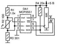
Мне нужно как можно точнее определить температуру. Поискав, нашел такую схему:
Собрал схему в proteus'е.

Нашел пример кода работы с этой микросхемой
// Arduino program to read Microchip MCP3550-60 using SPI bus
// by John Beale www.bealecorner.com Feb. 9 2012

/* =======================================================
MCP3550 is a differential input 22-bit ADC (21 bits + sign)
+Fullscale = (+Vref -1 LSB) = 0x1fffff
-Fullscale = (-Vref) = 0x200000
1 LSB => Vref / 2^21    for Vref=2 V, 1 LSB = 0.95 uV
Datasheet Spec: noise = 2.5 uV RMS with Vref = 2.5 V
measured results:
Noise Test setup: Vdd = 5V, +Vin = -Vin = Vref/2, Zin = 500 ohms (2x 1k divider)
with Vref = 0.500 V, RMS noise = 8.60 LSB or 2.05 uV  (1 LSB = 0.24 uV)
with Vref = 1.000 V, RMS noise = 4.33 LSB or 2.06 uV  (1 LSB = 0.48 uV)
with Vref = 2.048 V, RMS noise = 2.16 LSB or 2.12 uV  (1 LSB = 0.98 uV)
with Vref = 4.00 V,  RMS noise = 1.24 LSB or 2.37 uV  (1 LSB = 1.91 uV)
==========================================================
*/

#include <SPI.h> // use Arduino SPI library

#define CS 8     // bring CS high for ADC sleep mode, low to start new conversion
#define MOSI 11  // MOSI is not used for this device
#define MISO 12  // status and data bits from ADC
#define SCK 13   // SPI clock from Arduino to ADC

int samples = 100;    // how many samples to group together for avg. and std.dev
                   // MCP3550-60 does 15 samples per second (max) or 66.7 msec per sample

void setup() {
 Serial.begin(9600);
 SPI.begin();
 SPI.setClockDivider(SPI_CLOCK_DIV32);	// SPI clock rate < 5 MHz per MCP3550 spec
 SPI.setBitOrder(MSBFIRST);		// MSB or LSB first
 SPI.setDataMode(SPI_MODE3);		// rising/falling edge of clock

 digitalWrite(CS,HIGH);
 pinMode(CS, OUTPUT);  // CS (out from Arduino)
 pinMode(MOSI, OUTPUT);  //MOSI (data out from Arduino)
 pinMode(MISO, INPUT);  // MISO (data in to Arduino)
 pinMode(SCK, OUTPUT); // SCK  (serial clock)
 Serial.print("# MCP3550-60 ADC-Read v0.2 Feb.9 2012 sample size: ");
 Serial.println(samples);
 Serial.println("hours,value,stdev,min,max");
} // end setup()

void loop() {
 byte r1, r2, r3, r4;
 byte OVL, OVH;      // overload condition HIGH and LOW, respectively
 unsigned int i;              // loop counter
 unsigned long w;
 long x;
 long minval, maxval;
 double sum, mean, m2, delta, sumsq, variance,stdev;
 double hours;

 sum = 0;
 sumsq = 0;
 m2 = 0;
 mean = 0;
 minval=1E9;
 maxval=-1E9;

 for (int n=0;n<samples;) {
   digitalWrite(CS,HIGH);
   delayMicroseconds(100);
   digitalWrite(CS,LOW);   // start next conversion
   delay(50);            // delay in milliseconds (nominal MCP3550-60 rate: 66.7 msec => 15 Hz)
   i=0;                // use i as loop counter
   do {
     i++;
     delayMicroseconds(50);                            // loop keeps trying for up to 1 second
   } while ((digitalRead(MISO)==HIGH) && (i < 20000));   // wait for bit to drop low (ready)

   w = readword();    // data in:  32-bit word gets 24 bits via SPI port
   OVL = ((w & 0x80000000) != 0x00000000);  // ADC negative overflow bit (input > +Vref)
   OVH = ((w & 0x40000000) != 0x00000000);  // ADC positive overflow bit (input < -Vref)

   if ((i < 10000)) {
     n++;
     x = w <<2;  // to use the sign bit
     x = x/1024; // to move the LSB to bit 0 position
     if (x>maxval) maxval = x;
     if (x<minval) minval = x;
//      Serial.println(x);
     delta = x - mean;
     mean += delta/n;
     if (n > 1) {        // from http://en.wikipedia.org/wiki/Algorithms_for_calculating_variance
       m2 += delta * (x - mean);
     }
   }
 } // end for i..

 variance = m2/samples;
 stdev = sqrt(variance);
 hours = millis()/3600000.0;  // convert milliseconds to hours
 Serial.print(hours,4);
 Serial.print(",");
 Serial.print(mean);
 Serial.print(",");
 Serial.print(stdev);
 Serial.print(",");
 Serial.print(minval);
 Serial.print(",");
 Serial.print(maxval);
 Serial.println();

} // end main loop()


// ===================================================
// read one word from 22-bit ADC device  MCP3550

unsigned long readword() {
  union {
   unsigned long svar;
   byte c[4];
 } w;        // allow access to 4-byte word, or each byte separately

 w.c[3] = SPI.transfer(0x00);  // fill 3 bytes with data: 22 bit signed int + 2 overflow bits
 w.c[2] = SPI.transfer(0x00);
 w.c[1] = SPI.transfer(0x00);
 w.c[0]=0x00;                  // low-order byte set to zero

 return(w.svar);    // return unsigned long word
} // end readword()
В итоге в симуляторе arduino подвисает на этой части кода
w.c[3] = SPI.transfer(0x00); // fill 3 bytes with data: 22 bit signed int + 2 overflow bits
Кто знает в чем может быть причина, может я какую ни будь тонкость пропустил?


Тонкость - симулятор. В реале всё работает. По крайней мере вот этот кусок выдает код:
  		union{
			int32_t myByteCode;
			uint8_t aByte[4];
		}c ;

  	       digitalWrite(MCPPin,LOW);
               delay(76);

        	SPI.begin();
		SPI.setClockDivider(SPI_CLOCK_DIV32);
		SPI.setBitOrder(MSBFIRST);
		SPI.setDataMode(SPI_MODE0);

		c.aByte[3] = 0x00;
		c.aByte[2] = SPI.transfer(0);
		c.aByte[1] = SPI.transfer(0);
		c.aByte[0] = SPI.transfer(0);

                SPI.end();

               digitalWrite(MCPPin,HIGH);
               fl1=float(c.myByteCode);
Задержку 76 мс подбирал специально для моего корпуса.
Благодарю за ответ.