Протокол GS232(B,A) реализация, непонятное
- Войдите на сайт для отправки комментариев
Чт, 17/11/2016 - 09:05

Нашёл в сети реализацию этого протокола для Ардуино.
Вопрос! Зачем автор вводит задержку, да еще в секунду между считываниями из COM порта?
/*
VE2DX Arduino based GS232Bdruino rotor controller version 1.3.0

The goal of this project is to use a simple Arduino controller to control a rotor via HRD Rotator or any other rotor controller application on a PC.

The first series of test in this application will be to see if I can decode 	GS232B commands and respond back to the application using the Yaesu/Kempro GS232B response command set. In this release the M, C and S commands were implemented.

The actual tests were done using 2 LEDs in place of the rotor control outputs and a variable resistor in place of the rotor position feedback.

Simulation were done using VBB3 simulation and later tested on a FreeDuino and a DFR Romeo Arduino unit.

This is designed to be working with the GS232B-AZ protocols; I left some notes in the code on how to convert it into a GS232A unit. Basically all you need to do to convert from GS232B to GS232A is to simply change the values of the AZ from “AZ=” to “+0”, AZ0 from “AZ=0” to “+00” and AZ00 from “AZ=00” to “+000”.

Richard WTF is a “check fern!”; French Canadian running gag from old TV add of the 90’s, serious I use “Check Fern” as a series of simple serial port outputs to monitor specific variable status while trouble shooting the code, these should all be commented out at this time…

Outstanding bugs to be tested:
- Speed relay output not reacting properly.
- More LCD testing and optimisation needed...

Outstanding features to be worked on:
- Calibration
- 450 degree rotors
- add manual control switches (CW and CCW)
- speed indicator (LCD or LED?)
- making dual axis versions
- making DCU-1 version
- protocol autodetect

73

Richard ve2dx

EC info
1.0.0 March 6 2011 Original release
1.0.1 March 7 2011 corrected CW and CCW display were reversed on LCD, corrected naming issues.
1.0.2 March 7 2011 corrected string handling programing error...
1.1.0 March 8 2011 first try at serial controlled operation, restructured code, added GS232A conversion notes
1.1.1 March 9 2011 ok fixed the string to int issue while decoding MBBB command…tough read up on toInt() command!!!
1.2.0 March 9 2011 cleaned up code, split app in subroutine add speed control
*/


// include the library code:
// #include <LiquidCrystal.h>
// LiquidCrystal lcd(12, 11, 2, 3, 4, 5) ;						// initialize the library with the numbers of the interface pins

#include <OLED_I2C.h>
OLED  myOLED(SDA, SCL, 8);
extern uint8_t TinyFont[];
extern uint8_t SmallFont[];


int AZ1input = 2; 								// set pin 2 as my input for the azimuth reference feedback.
int CW1output = 6;								// set pin 6 as my output to turn the rotor Clockwise.
int CCW1output = 7; 								// set pin 7 as my output to turn the rotor Counter Clockwise.
long AZreal = 0;								// set AZreal as a Long numeric value with default of 0, this is my real bearing
long AZrequested = 0; 								// set AZrequested as a numeric value with default of 0, this is my requested bearing
long AZtemp = 0;								// set the temp start from bearing when doing movement...
int CW1speed = 8;								// set pin 8 as the speed control output
char serialdata;								// define my serialdata variable as char
String serialstring, AZmove, AZdirection, GS232Boutput, AZ00, AZ0, AZ, Mid;	// defining all my possible strings

void setup() {									// setup loop

	/*
	lcd.begin(16, 2);							// set up the LCD's number of rows and columns:
										            // we are using a 2 rows by 16 character LCD
  */
  myOLED.begin();
  myOLED.setFont(SmallFont);

	pinMode(AZ1input, INPUT); 						// Set AZ1input previously ided as pin 8 as an INPUT
	pinMode(CW1output, OUTPUT); 					// CW1output (pin 6) is now defined as an Output
	pinMode(CCW1output, OUTPUT);					// CCW1output (pin 7) is now defined as an Output
	pinMode(CW1speed, OUTPUT);						// CW1speed (pin 8) is now defined as an Output
	AZ00 = String("AZ=00");							  // Set AZ00 string, for GS232A conversion simply use “+00”
	AZ0 = String("AZ=0");							    // Set AZ0 string, for GS232A conversion simply use “+0”
	AZ = String("AZ=");							      // Set AZ string, for GS232A conversion simply use “+”
	Mid = String(" : ");							    // Set Middle string for LCD display
	digitalWrite(CCW1output, LOW);				// Turn OFF CounterClockwise relay
  digitalWrite(CW1output, LOW);					// Turn OFF Clockwise relay

	Serial.begin(9600);							      // opens serial port sets data rate to 9600 bps

	AZrequested = (analogRead(AZ1input));		 // first we set the AZresquest equal to present bearing
	AZrequested = (AZrequested * 100 / 284); // conversion of result in degrees
										                       // dividing the AZreal (0 - 1023) by 2.84
}

void RealBearing() {								    // this is my subroutine that gets the bearing info and converts it
										                    // into degrees
	AZreal = (analogRead(AZ1input));			// Set AZreal equal to input voltage from Bearing indicator
	AZreal = (AZreal * 100 / 284);				// now we will define the value of AZreal to a 0-360 setting by
										                    // dividing the AZreal (0 - 1023) by 2.84
}


void GetSerialData() {								  // this is my subroutine that gets the GS232 data from the serial port

	//if (Serial.available() > 0) {				                // Is there any data for me on the serial port?
	//Serial.println("GS232B command! lets read it!"); 		// check fern

		serialdata = Serial.read(); 				// Lets read the data from the serial port

	//serialdata = byte (serialdata);					// convert the data in text

		Serial.println(); 					        // check fern
    delay (1000); //??? непонятки

// we need to respond to a C command with bearing info under the following format
// AZ=BBB where BBB is the bearing info with leading zeros.

		if (serialdata == 'C') { 					 // if data received on serial port is equal to the letter C or c then we send
										                   // the AZ=BBB response via the serial port.
										                   //Serial.println("detected C command");		        // check fern
		if (AZreal > 99) {					       // check if bearing is 3 digit (100 or more)
										                   // GS232A or B protocol dictates that the bearing must have leading zeros
String GS232Boutput = (AZ + AZreal);	 // setting my output string for the serial port (AZ=+AZreal)
Serial.println(GS232Boutput); 			   // output my position as GS232B (or GS232A if code was mods) protocol
			}							                   // end of IF
			else {							             // if wasnt 3 digit then
				if (AZreal < 10) {				     // check if bearing is a single digit (9 or less)
					String GS232Boutput = (AZ00 + AZreal);	// setting my output string for the serial port (AZ=00+AZreal)
					Serial.println(GS232Boutput); 		      // output my position as GS232B (or GS232A if code was mods) protocol
				}						                              // end of IF
				else  {						                      // then bearing should be 2 digit (10 to 99)
					String GS232Boutput = (AZ0 + AZreal);	// setting my output string for the serial port (AZ=0+AZreal)
					Serial.println(GS232Boutput); 		    // output my position as GS232B (or GS232A if code was mods) protocol
				}						// end of IF
			}							// end of IF
		}								// end of IF

// Next we will define our destination bearing
// we look for MBBB command from the serial port by detecting the M then getting the 3 digit bearing info BBB.

		if (serialdata == 'M') { 					// if data received on serial port is equal to the letter M then
										                  // start looking for the next 3 numerical digit these will be requested
			                                //Serial.println("detected M command");			// check fern
			digitalWrite(CCW1output, LOW);	// Turn OFF Counter Clockwise relay
			digitalWrite(CW1output, LOW);		// Turn OFF Clockwise relay
			digitalWrite(CW1speed, LOW);		// Turn OFF Speed relay
			int X = 0;						          // set my counter (X) to 0
			String serialstring;					  // I need this to clear the serialstring value
			while (X < 3) {						      // check to see the value of my counter as long as it is not equal to 3
				//Serial.println(X);				  // check fern
				serialdata = Serial.read(); 	// ok lets read the first byte of data
				                              //serialdata = byte (serialdata);			// convert it to text
				serialstring = String (serialstring + serialdata);	// Assemble it with the previous character (or number)
				                              //Serial.println(serialdata);			// check fern
				                              //Serial.println(serialstring);			// check fern again
				X = X++;					            // increment my counter by 1
			}							                  // end of WHILE
			                                //Serial.println(serialstring);				// check fern resulting text
			AZrequested = serialstring.toInt();			// set my requested bearing eual to convert resulting serial 3 digit datatext
										                  // to do so I need to convert the string into integer (read up on toInt() command!!!)
			AZtemp = AZreal;					      // for speed control I must set a start point its AZtemp
		}								                  // end of IF


// Now lets see if we got an ALL STOP command (S)?

		if (serialdata == 'S') { 					// if data received on serial port is equal to the letter C then we send
										                  // the AZ=BBB response via the serial port.
			                                //Serial.println("detected S command");			// check fern
			digitalWrite(CCW1output, LOW);	// Turn OFF Counter Clockwise relay
			digitalWrite(CW1output, LOW);		// Turn OFF Clockwise relay
			digitalWrite(CW1speed, LOW);		// Turn OFF Speed relay
			AZrequested = AZreal;					  // set AZrequested equal to AZreal, I stop the rotor by making them equal
			                                //Serial.println(AZrequested);				// check fern
		}								                  // End of IF
	                                    //}
}

void MoveAndDisplay() {								// this is my subroutine that moves the rotor and keeps LCD display updated

	                                    //before we do I will send myself on the serial port the resulting Requested, real and start up bearings
		                                  //Serial.println(AZrequested);					// check fern
		                                  //Serial.println(AZreal);					// check fern
		                                  //Serial.println(AZtemp);					// check fern
		                                  //delay (1000);							// check fern wait a little so I can see
	                                    // these were rem out after debuging

	if (AZreal > AZrequested) {					// action if Real Bearing is Greater then Requested bearing
		digitalWrite(CW1output, LOW);			// Turn OFF Clockwise relay
		digitalWrite(CCW1output, HIGH);		// Turn ON Counter Clockwise relay
		AZmove = String("  CCW");					// Set the activity portion of the display to CCW
		lcdroutine();							        // call LCD routine
		SpeedControl(); 						      // Speed control routine
	}									                  // end of IF


	if (AZreal < AZrequested) {					// action if Real Bearing is less then requested bearing
		digitalWrite(CCW1output, LOW);		// Turn OFF Counter Clockwise relay
		digitalWrite(CW1output, HIGH);		// Turn ON Clockwise relay
		AZmove = String("   CW");         // Set the activity portion of the display to CW
		lcdroutine();							        // call LCD routine
		SpeedControl(); 						      // Speed control routine
	}									                  // end of IF

	if (AZreal == AZrequested) {				// action if Real Bearing is equal to requested bearing
		digitalWrite(CCW1output, LOW);		// Turn OFF Counter Clockwise relay
		digitalWrite(CW1output, LOW);			// Turn OFF Clockwise relay
		digitalWrite(CW1speed, LOW);			// Turn OFF Speed relay
		AZmove = String("     ");         // Set the activity portion of the display to BLANK
		lcdroutine();							        // call LCD routine
	}									                  // end of IF
}

/*
void lcdroutine() {								    // this is my subroutine that LCD display routine

		String AZdirection = (AZ + AZreal + Mid + AZrequested + AZmove);	// set the LCD data for line
										                  // Now I will display on the LCD the real (AAA) and requested (BBB)
										                  // values and activity (CCC)(AZ AAA : BBB CCC)
		lcd.clear(); 							        // clear the LCD, this is important to prevent unwanted garbage in LCD
		lcd.setCursor(0, 0);						  // set the cursor to column 0, line 0
		lcd.print("VE2DX,GS232Bduino");		// print on the first line our ID and braging rights!
		lcd.setCursor(0, 1);						  // set the cursor to column 0, line 1 (note: line 1 is the second row,
										                  // since counting begins with 0):
		lcd.print(AZdirection);						// Display on LCD resulting Action
}
*/
void lcdroutine() {                    // this is my subroutine that OLED display routine

    String AZdirection = (AZ + AZreal + Mid + AZrequested + AZmove);  // set the OLED data for line
                                      // Now I will display on the OLED the real (AAA) and requested (BBB)
                                      // values and activity (CCC)(AZ AAA : BBB CCC)
      myOLED.print("VE2DX,GS232Bduino", CENTER, 16);
      myOLED.print(AZdirection, CENTER, 28);
      myOLED.update();
}

void SpeedControl() {								  // this is my subroutine that controls the speed of the rotor
	// Serial.println("SPEED CHECK");		// check fern
	if (AZreal > AZrequested) {					// as long as bearing in greater then destination
 		                                  // Serial.println("This portion should apply when going CCW");	// check fern
		if (AZreal < (AZrequested + 10)) {// Check to see if my real bearing is less then 10 degrees from my destination point
			                                // Serial.println("SPEED CHECK CCW LOW");		// check fern
			digitalWrite(CW1speed, LOW);		// Turn OFF Speed relay
		} else {							            //
			if (AZtemp > (AZreal + 10)) {		// Check to see if my real bearing is more then 10 degrees from my start point
				                              // Serial.println("SPEED CHECK CCW HIGH");	// check fern
				digitalWrite(CW1speed, HIGH);	// Turn ON Speed relay
			}							                  // end of IF
		}								                  // end of IF
	}									                  // end of IF
	if (AZreal < AZrequested) {					// as long as bearing in less then destination
 		                                  //Serial.println("This portion should apply when going CW");	// check fern
		if (AZreal > (AZrequested - 10)) {// Check to see if my real bearing is less then 10 degrees from my destination point
			                                //Serial.println("SPEED CHECK CW LOW");			// check fern
			digitalWrite(CW1speed, LOW);		// Turn OFF Speed relay
		} else {							            //
  			if (AZtemp < (AZreal - 10)) {	// Check to see if my real bearing is more then 10 degrees from my start point
				                              //Serial.println("SPEED CHECK CW HIGH");	// check fern
				digitalWrite(CW1speed, HIGH);	// Turn ON Speed relay
			}							                  // end of IF
		}								                  // end of IF
	}									                  // end of IF
}										                  // end of IF


void loop() {									        // Lets get things started

// Ok First, we will look at our real bearing convert the incoming voltage into degrees

	RealBearing() ;								      // Start RealBearing routine.

// Ok now we are going to see if we are getting any request on the serial port, it is running at 9600bps

	GetSerialData();							      // next we get and check data from the serial port comparing it to protocol

// next lets display on the LCD the info regarding present operations of the GS232Bduino

	MoveAndDisplay();							      // and finally we move the rotor and display the related info on the LCD

}
спроси у автора скетча, зачем он так сделал.
спроси у автора скетча, зачем он так сделал.
говорит, что без оного пропуски с порта были
спроси у автора скетча, зачем он так сделал.
говорит, что без оного пропуски с порта были
это он закомментил или ты?
//if (Serial.available() > 0) { // Is there any data for me on the serial port?где оригинальный скетч?
Я стараюсь изъясняться по русски )))
ОН!
Оригинальный на arduino.cc (ссылку не сохранил)
Взято здесь
Из моих экзерцизов перевод на другой дисплей всего
Поправил код для сборки под 1.6.12
/* VE2DX Arduino based GS232Bdruino rotor controller version 1.3.0 The goal of this project is to use a simple Arduino controller to control a rotor via HRD Rotator or any other rotor controller application on a PC. The first series of test in this application will be to see if I can decode GS232B commands and respond back to the application using the Yaesu/Kempro GS232B response command set. In this release the M, C and S commands were implemented. The actual tests were done using 2 LEDs in place of the rotor control outputs and a variable resistor in place of the rotor position feedback. Simulation were done using VBB3 simulation and later tested on a FreeDuino and a DFR Romeo Arduino unit. This is designed to be working with the GS232B-AZ protocols; I left some notes in the code on how to convert it into a GS232A unit. Basically all you need to do to convert from GS232B to GS232A is to simply change the values of the AZ from “AZ=” to “+0”, AZ0 from “AZ=0” to “+00” and AZ00 from “AZ=00” to “+000”. Richard WTF is a “check fern!”; French Canadian running gag from old TV add of the 90’s, serious I use “Check Fern” as a series of simple serial port outputs to monitor specific variable status while trouble shooting the code, these should all be commented out at this time… Outstanding bugs to be tested: - Speed relay output not reacting properly. - More LCD testing and optimisation needed... Outstanding features to be worked on: - Calibration - 450 degree rotors - add manual control switches (CW and CCW) - speed indicator (LCD or LED?) - making dual axis versions - making DCU-1 version - protocol autodetect 73 Richard ve2dx EC info 1.0.0 March 6 2011 Original release 1.0.1 March 7 2011 corrected CW and CCW display were reversed on LCD, corrected naming issues. 1.0.2 March 7 2011 corrected string handling programing error... 1.1.0 March 8 2011 first try at serial controlled operation, restructured code, added GS232A conversion notes 1.1.1 March 9 2011 ok fixed the string to int issue while decoding MBBB command…tough read up on toInt() command!!! 1.2.0 March 9 2011 cleaned up code, split app in subroutine add speed control */ // include the library code: // #include <LiquidCrystal.h> // LiquidCrystal lcd(12, 11, 2, 3, 4, 5) ; // initialize the library with the numbers of the interface pins #include <OLED_I2C.h> OLED myOLED(SDA, SCL, 8); extern uint8_t TinyFont[]; extern uint8_t SmallFont[]; int AZ1input = 2; // set pin 2 as my input for the azimuth reference feedback. int CW1output = 6; // set pin 6 as my output to turn the rotor Clockwise. int CCW1output = 7; // set pin 7 as my output to turn the rotor Counter Clockwise. long AZreal = 0; // set AZreal as a Long numeric value with default of 0, this is my real bearing long AZrequested = 0; // set AZrequested as a numeric value with default of 0, this is my requested bearing long AZtemp = 0; // set the temp start from bearing when doing movement... int CW1speed = 8; // set pin 8 as the speed control output char serialdata; // define my serialdata variable as char String serialstring, AZmove, AZdirection, GS232Boutput, AZ00, AZ0, AZ, Mid; // defining all my possible strings void setup() { // setup loop /* lcd.begin(16, 2); // set up the LCD's number of rows and columns: // we are using a 2 rows by 16 character LCD */ myOLED.begin(); myOLED.setFont(SmallFont); pinMode(AZ1input, INPUT); // Set AZ1input previously ided as pin 8 as an INPUT pinMode(CW1output, OUTPUT); // CW1output (pin 6) is now defined as an Output pinMode(CCW1output, OUTPUT); // CCW1output (pin 7) is now defined as an Output pinMode(CW1speed, OUTPUT); // CW1speed (pin 8) is now defined as an Output AZ00 = String("AZ=00"); // Set AZ00 string, for GS232A conversion simply use “+00” AZ0 = String("AZ=0"); // Set AZ0 string, for GS232A conversion simply use “+0” AZ = String("AZ="); // Set AZ string, for GS232A conversion simply use “+” Mid = String(" : "); // Set Middle string for LCD display digitalWrite(CCW1output, LOW); // Turn OFF CounterClockwise relay digitalWrite(CW1output, LOW); // Turn OFF Clockwise relay Serial.begin(9600); // opens serial port sets data rate to 9600 bps AZrequested = (analogRead(AZ1input)); // first we set the AZresquest equal to present bearing AZrequested = (AZrequested * 100 / 284); // conversion of result in degrees // dividing the AZreal (0 - 1023) by 2.84 } void RealBearing() { // this is my subroutine that gets the bearing info and converts it // into degrees AZreal = (analogRead(AZ1input)); // Set AZreal equal to input voltage from Bearing indicator AZreal = (AZreal * 100 / 284); // now we will define the value of AZreal to a 0-360 setting by // dividing the AZreal (0 - 1023) by 2.84 } void GetSerialData() { // this is my subroutine that gets the GS232 data from the serial port //if (Serial.available() > 0) { // Is there any data for me on the serial port? //Serial.println("GS232B command! lets read it!"); // check fern serialdata = Serial.read(); // Lets read the data from the serial port //serialdata = byte (serialdata); // convert the data in text Serial.println(); // check fern delay (1000); //??? непонятки // we need to respond to a C command with bearing info under the following format // AZ=BBB where BBB is the bearing info with leading zeros. if (serialdata == 'C') { // if data received on serial port is equal to the letter C or c then we send // the AZ=BBB response via the serial port. //Serial.println("detected C command"); // check fern if (AZreal > 99) { // check if bearing is 3 digit (100 or more) // GS232A or B protocol dictates that the bearing must have leading zeros String GS232Boutput = (AZ + AZreal); // setting my output string for the serial port (AZ=+AZreal) Serial.println(GS232Boutput); // output my position as GS232B (or GS232A if code was mods) protocol } // end of IF else { // if wasnt 3 digit then if (AZreal < 10) { // check if bearing is a single digit (9 or less) String GS232Boutput = (AZ00 + AZreal); // setting my output string for the serial port (AZ=00+AZreal) Serial.println(GS232Boutput); // output my position as GS232B (or GS232A if code was mods) protocol } // end of IF else { // then bearing should be 2 digit (10 to 99) String GS232Boutput = (AZ0 + AZreal); // setting my output string for the serial port (AZ=0+AZreal) Serial.println(GS232Boutput); // output my position as GS232B (or GS232A if code was mods) protocol } // end of IF } // end of IF } // end of IF // Next we will define our destination bearing // we look for MBBB command from the serial port by detecting the M then getting the 3 digit bearing info BBB. if (serialdata == 'M') { // if data received on serial port is equal to the letter M then // start looking for the next 3 numerical digit these will be requested //Serial.println("detected M command"); // check fern digitalWrite(CCW1output, LOW); // Turn OFF Counter Clockwise relay digitalWrite(CW1output, LOW); // Turn OFF Clockwise relay digitalWrite(CW1speed, LOW); // Turn OFF Speed relay int X = 0; // set my counter (X) to 0 String serialstring; // I need this to clear the serialstring value while (X < 3) { // check to see the value of my counter as long as it is not equal to 3 //Serial.println(X); // check fern serialdata = Serial.read(); // ok lets read the first byte of data //serialdata = byte (serialdata); // convert it to text serialstring = String (serialstring + serialdata); // Assemble it with the previous character (or number) //Serial.println(serialdata); // check fern //Serial.println(serialstring); // check fern again X = X++; // increment my counter by 1 } // end of WHILE //Serial.println(serialstring); // check fern resulting text AZrequested = serialstring.toInt(); // set my requested bearing eual to convert resulting serial 3 digit datatext // to do so I need to convert the string into integer (read up on toInt() command!!!) AZtemp = AZreal; // for speed control I must set a start point its AZtemp } // end of IF // Now lets see if we got an ALL STOP command (S)? if (serialdata == 'S') { // if data received on serial port is equal to the letter C then we send // the AZ=BBB response via the serial port. //Serial.println("detected S command"); // check fern digitalWrite(CCW1output, LOW); // Turn OFF Counter Clockwise relay digitalWrite(CW1output, LOW); // Turn OFF Clockwise relay digitalWrite(CW1speed, LOW); // Turn OFF Speed relay AZrequested = AZreal; // set AZrequested equal to AZreal, I stop the rotor by making them equal //Serial.println(AZrequested); // check fern } // End of IF //} } void lcdroutine() { // this is my subroutine that OLED display routine String AZdirection = (AZ + AZreal + Mid + AZrequested + AZmove); // set the OLED data for line // Now I will display on the OLED the real (AAA) and requested (BBB) // values and activity (CCC)(AZ AAA : BBB CCC) myOLED.print("VE2DX,GS232Bduino", CENTER, 16); myOLED.print(AZdirection, CENTER, 28); myOLED.update(); } void SpeedControl() { // this is my subroutine that controls the speed of the rotor // Serial.println("SPEED CHECK"); // check fern if (AZreal > AZrequested) { // as long as bearing in greater then destination // Serial.println("This portion should apply when going CCW"); // check fern if (AZreal < (AZrequested + 10)) {// Check to see if my real bearing is less then 10 degrees from my destination point // Serial.println("SPEED CHECK CCW LOW"); // check fern digitalWrite(CW1speed, LOW); // Turn OFF Speed relay } else { // if (AZtemp > (AZreal + 10)) { // Check to see if my real bearing is more then 10 degrees from my start point // Serial.println("SPEED CHECK CCW HIGH"); // check fern digitalWrite(CW1speed, HIGH); // Turn ON Speed relay } // end of IF } // end of IF } // end of IF if (AZreal < AZrequested) { // as long as bearing in less then destination //Serial.println("This portion should apply when going CW"); // check fern if (AZreal > (AZrequested - 10)) {// Check to see if my real bearing is less then 10 degrees from my destination point //Serial.println("SPEED CHECK CW LOW"); // check fern digitalWrite(CW1speed, LOW); // Turn OFF Speed relay } else { // if (AZtemp < (AZreal - 10)) { // Check to see if my real bearing is more then 10 degrees from my start point //Serial.println("SPEED CHECK CW HIGH"); // check fern digitalWrite(CW1speed, HIGH); // Turn ON Speed relay } // end of IF } // end of IF } // end of IF } // end of IF void MoveAndDisplay() { // this is my subroutine that moves the rotor and keeps LCD display updated //before we do I will send myself on the serial port the resulting Requested, real and start up bearings //Serial.println(AZrequested); // check fern //Serial.println(AZreal); // check fern //Serial.println(AZtemp); // check fern //delay (1000); // check fern wait a little so I can see // these were rem out after debuging if (AZreal > AZrequested) { // action if Real Bearing is Greater then Requested bearing digitalWrite(CW1output, LOW); // Turn OFF Clockwise relay digitalWrite(CCW1output, HIGH); // Turn ON Counter Clockwise relay AZmove = String(" CCW"); // Set the activity portion of the display to CCW lcdroutine(); // call LCD routine SpeedControl(); // Speed control routine } // end of IF if (AZreal < AZrequested) { // action if Real Bearing is less then requested bearing digitalWrite(CCW1output, LOW); // Turn OFF Counter Clockwise relay digitalWrite(CW1output, HIGH); // Turn ON Clockwise relay AZmove = String(" CW"); // Set the activity portion of the display to CW lcdroutine(); // call LCD routine SpeedControl(); // Speed control routine } // end of IF if (AZreal == AZrequested) { // action if Real Bearing is equal to requested bearing digitalWrite(CCW1output, LOW); // Turn OFF Counter Clockwise relay digitalWrite(CW1output, LOW); // Turn OFF Clockwise relay digitalWrite(CW1speed, LOW); // Turn OFF Speed relay AZmove = String(" "); // Set the activity portion of the display to BLANK lcdroutine(); // call LCD routine } // end of IF } /* void lcdroutine() { // this is my subroutine that LCD display routine String AZdirection = (AZ + AZreal + Mid + AZrequested + AZmove); // set the LCD data for line // Now I will display on the LCD the real (AAA) and requested (BBB) // values and activity (CCC)(AZ AAA : BBB CCC) lcd.clear(); // clear the LCD, this is important to prevent unwanted garbage in LCD lcd.setCursor(0, 0); // set the cursor to column 0, line 0 lcd.print("VE2DX,GS232Bduino"); // print on the first line our ID and braging rights! lcd.setCursor(0, 1); // set the cursor to column 0, line 1 (note: line 1 is the second row, // since counting begins with 0): lcd.print(AZdirection); // Display on LCD resulting Action } */ void loop() { // Lets get things started // Ok First, we will look at our real bearing convert the incoming voltage into degrees RealBearing() ; // Start RealBearing routine. // Ok now we are going to see if we are getting any request on the serial port, it is running at 9600bps GetSerialData(); // next we get and check data from the serial port comparing it to protocol // next lets display on the LCD the info regarding present operations of the GS232Bduino MoveAndDisplay(); // and finally we move the rotor and display the related info on the LCD }тогда нужно раскомментить //if (Serial.available() > 0) {
убрать делей и собирать символы в строку... насколько я понял полёт безумной мысли автора скетча.
зачем он творит странное, например тут
    if (serialdata == 'M') {          // if data received on serial port is equal to the letter M then
////                     // set my counter (X) to 0
      String serialstring;            // I need this to clear the serialstring value
      while (X < 3) {                 // check to see the value of my counter as long as it is not equal to 3
        //Serial.println(X);          // check fern
        serialdata = Serial.read();   // ok lets read the first byte of data
                                      //serialdata = byte (serialdata);     // convert it to text
        serialstring = String (serialstring + serialdata);  // Assemble it with the previous character (or number)
////                    // increment my counter by 1
      }                               // end of WHILE
///              // for speed control I must set a start point its AZtemp
    }
мне не понятно.
это что он творит? считал символ 'M' из порта, вместо того, что бы его сохранить в строку, читает порт, теряя этот символ... но! в приёмном буфере порта на этот момент может быть только символ 'M' и больше ничего - отсюда пропуски?
выхода два один правильный, второй неправильный:
1. не делать так.
2. делать так, но if (Serial.available() > 4) { - типо ждать пока придёт четыре символа
Для поддержания канала связи в актуальном (поднятом) состоянии программа управления контроллером гонит в порт команду "С"
(один символ), если надо переместить АФУ по азимуту, то, да, тогда 4 символа, команда Mххх, если остановить, "S", тут главное не пропустить, не царское это дело повторять контроллеру (ну так придумали япошки этот протокол), и команд там не три и у каждой свой синтаксис, это он реализовал только три...
на эту команду - "C" контрллер должен отдавать актуальное состояние азимута со своих датчиков - команда Oxxx
Все пишут, что протокол очень простой, но только коды не выкладывают, стесняютСИ
А Ричард так и писал на всех форумах, просветите лузера
Да, кстати, я тут уже спрашивал МИСТЕРА 7 ТЫСЯЧ насчёт протоколов обмена, сказал в лёгкую ))) мужчина сказал мужчина сделал!
я тебе объяснил, в каком месте происходит потеря инфы - глупо надеяться, что считав один символ из приёмного буфера порта, там будет что-то ещё.
*дальше не смотрел - код уёпищьный.
нужно слать символы в порт - шли.
пришло что-то в ответ - принимай посимвольно, складывай в строку, анализируй содержимое строки, что-то делай, если пришло нужное.
Да, кстати, я тут уже спрашивал МИСТЕРА 7 ТЫСЯЧ насчёт протоколов обмена, сказал в лёгкую ))) мужчина сказал мужчина сделал!
кому ты это написал и зачем?
я тебе объяснил, в каком месте происходит потеря инфы - глупо надеяться, что считав один символ из приёмного буфера порта, там будет что-то ещё.
*дальше не смотрел - код уёпищьный.
нужно слать символы в порт - шли.
пришло что-то в ответ - принимай посимвольно, складывай в строку, анализируй содержимое строки, что-то делай, если пришло нужное.
K3NG в принципе так и сделал
process_yaesu_command(control_port_buffer,control_port_buffer_index,CONTROL_PORT0,return_string);
#ifdef FEATURE_YAESU_EMULATION void process_yaesu_command(byte * yaesu_command_buffer, int yaesu_command_buffer_index, byte source_port, char * return_string){ char tempstring[11] = ""; int parsed_value = 0; int parsed_elevation = 0; #ifdef FEATURE_TIMED_BUFFER int parsed_value2 = 0; #endif //FEATURE_TIMED_BUFFER strcpy(return_string,""); switch (yaesu_command_buffer[0]) { // look at the first character of the command case 'C': // C - return current azimuth #ifdef DEBUG_PROCESS_YAESU if (debug_mode) { debug.print("yaesu_serial_command: C\n"); } #endif // DEBUG_PROCESS_YAESU #ifdef OPTION_DELAY_C_CMD_OUTPUT delay(400); #endif //strcpy(return_string,""); #ifndef OPTION_GS_232B_EMULATION strcat(return_string,"+0"); #else strcat(return_string,"AZ="); #endif dtostrf(int(azimuth / HEADING_MULTIPLIER),0,0,tempstring); if (int(azimuth / HEADING_MULTIPLIER) < 10) { strcat(return_string,"0"); } if (int(azimuth / HEADING_MULTIPLIER) < 100) { strcat(return_string,"0"); } strcat(return_string,tempstring); #ifdef FEATURE_ELEVATION_CONTROL #ifndef OPTION_C_COMMAND_SENDS_AZ_AND_EL if ((yaesu_command_buffer[1] == '2') && (yaesu_command_buffer_index > 1)) { // did we get the C2 command? #endif #ifndef OPTION_GS_232B_EMULATION if (elevation < 0) { strcat(return_string,"-0"); } else { strcat(return_string,"+0"); } #endif #ifdef OPTION_GS_232B_EMULATION strcat(return_string,"EL="); #endif dtostrf(int(elevation / HEADING_MULTIPLIER),0,0,tempstring); if (int(elevation / HEADING_MULTIPLIER) < 10) { strcat(return_string,("0")); } if (int(elevation / HEADING_MULTIPLIER) < 100) { strcat(return_string,"0"); } strcat(return_string,tempstring); #ifndef OPTION_C_COMMAND_SENDS_AZ_AND_EL } else { //strcat(return_string,"\n"); } #endif // OPTION_C_COMMAND_SENDS_AZ_AND_EL #endif // FEATURE_ELEVATION_CONTROL #ifndef FEATURE_ELEVATION_CONTROL if ((yaesu_command_buffer[1] == '2') && (yaesu_command_buffer_index > 1)) { // did we get the C2 command? #ifndef OPTION_GS_232B_EMULATION strcat(return_string,"+0000"); // return a dummy elevation since we don't have the elevation feature turned on #else strcat(return_string,"EL=000"); #endif } else { //strcat(return_string,"\n"); } #endif // FEATURE_ELEVATION_CONTROL break; //-----------------end of C command----------------- #ifdef FEATURE_AZ_POSITION_POTENTIOMETER case 'F': // F - full scale calibration #ifdef DEBUG_PROCESS_YAESU if (debug_mode) { debug.print("yaesu_serial_command: F\n"); } #endif // DEBUG_PROCESS_YAESU #ifdef FEATURE_ELEVATION_CONTROL if ((yaesu_command_buffer[1] == '2') && (yaesu_command_buffer_index > 1)) { // did we get the F2 command? clear_serial_buffer(); if (source_port == CONTROL_PORT0){ control_port->println(F("Elevate to 180 (or max elevation) and send keystroke...")); } get_keystroke(); read_elevation(1); configuration.analog_el_max_elevation = analog_el; write_settings_to_eeprom(); strcpy(return_string,"Wrote to memory"); return; } #endif clear_serial_buffer(); if (source_port == CONTROL_PORT0){ control_port->println(F("Rotate to full CW and send keystroke...")); get_keystroke(); } read_azimuth(1); configuration.analog_az_full_cw = analog_az; write_settings_to_eeprom(); strcpy(return_string,"Wrote to memory"); break; #endif // FEATURE_AZ_POSITION_POTENTIOMETER case 'H': print_help(source_port); break; // H - print help - depricated case 'L': // L - manual left (CCW) rotation #ifdef DEBUG_PROCESS_YAESU if (debug_mode) { debug.print("yaesu_serial_command: L\n"); } #endif // DEBUG_PROCESS_YAESU submit_request(AZ, REQUEST_CCW, 0, 21); //strcpy(return_string,"\n"); #ifdef FEATURE_PARK deactivate_park(); #endif // FEATURE_PARK break; #ifdef FEATURE_AZ_POSITION_POTENTIOMETER case 'O': // O - offset calibration #ifdef DEBUG_PROCESS_YAESU if (debug_mode) { debug.print("yaesu_serial_command: O\n"); } #endif // DEBUG_PROCESS_YAESU #ifdef FEATURE_ELEVATION_CONTROL if ((yaesu_command_buffer[1] == '2') && (yaesu_command_buffer_index > 1)) { // did we get the O2 command? clear_serial_buffer(); if (source_port == CONTROL_PORT0){ control_port->println(F("Elevate to 0 degrees and send keystroke...")); } get_keystroke(); read_elevation(1); configuration.analog_el_0_degrees = analog_el; write_settings_to_eeprom(); strcpy(return_string,"Wrote to memory"); return; } #endif clear_serial_buffer(); if (source_port == CONTROL_PORT0){ control_port->println(F("Rotate to full CCW and send keystroke...")); } get_keystroke(); read_azimuth(1); configuration.analog_az_full_ccw = analog_az; write_settings_to_eeprom(); strcpy(return_string,"Wrote to memory"); break; #endif // FEATURE_AZ_POSITION_POTENTIOMETER case 'R': // R - manual right (CW) rotation #ifdef DEBUG_PROCESS_YAESU if (debug_mode) { debug.print("yaesu_serial_command: R\n"); } #endif // DEBUG_PROCESS_YAESU submit_request(AZ, REQUEST_CW, 0, 22); strcpy(return_string,"\n"); #ifdef FEATURE_PARK deactivate_park(); #endif // FEATURE_PARK break; case 'A': // A - CW/CCW rotation stop #ifdef DEBUG_PROCESS_YAESU if (debug_mode) { debug.print("yaesu_serial_command: A\n"); } #endif // DEBUG_PROCESS_YAESU submit_request(AZ, REQUEST_STOP, 0, 23); //strcpy(return_string,"\n"); #ifdef FEATURE_PARK deactivate_park(); #endif // FEATURE_PARK break; case 'S': // S - all stop #ifdef DEBUG_PROCESS_YAESU if (debug_mode) { debug.print("yaesu_serial_command: S\n"); } #endif // DEBUG_PROCESS_YAESU submit_request(AZ, REQUEST_STOP, 0, 24); #ifdef FEATURE_ELEVATION_CONTROL submit_request(EL, REQUEST_STOP, 0, 25); #endif #ifdef FEATURE_TIMED_BUFFER clear_timed_buffer(); #endif // FEATURE_TIMED_BUFFER //strcpy(return_string,""); #ifdef FEATURE_PARK deactivate_park(); #endif // FEATURE_PARK break; case 'M': // M - auto azimuth rotation #ifdef DEBUG_PROCESS_YAESU if (debug_mode) { debug.print("yaesu_serial_command: M\n"); } #endif // DEBUG_PROCESS_YAESU #ifdef FEATURE_PARK deactivate_park(); #endif // FEATURE_PARK if (yaesu_command_buffer_index > 4) { // if there are more than 4 characters in the command buffer, we got a timed interval command #ifdef FEATURE_TIMED_BUFFER clear_timed_buffer(); parsed_value = ((int(yaesu_command_buffer[1]) - 48) * 100) + ((int(yaesu_command_buffer[2]) - 48) * 10) + (int(yaesu_command_buffer[3]) - 48); if ((parsed_value > 0) && (parsed_value < 1000)) { timed_buffer_interval_value_seconds = parsed_value; for (int x = 5; x < yaesu_command_buffer_index; x = x + 4) { parsed_value = ((int(yaesu_command_buffer[x]) - 48) * 100) + ((int(yaesu_command_buffer[x + 1]) - 48) * 10) + (int(yaesu_command_buffer[x + 2]) - 48); if ((parsed_value >= 0) && (parsed_value <= 360)) { // is it a valid azimuth? timed_buffer_azimuths[timed_buffer_number_entries_loaded] = parsed_value * HEADING_MULTIPLIER; timed_buffer_number_entries_loaded++; timed_buffer_status = LOADED_AZIMUTHS; if (timed_buffer_number_entries_loaded > TIMED_INTERVAL_ARRAY_SIZE) { // is the array full? submit_request(AZ, REQUEST_AZIMUTH, timed_buffer_azimuths[0], 26); // array is full, go to the first azimuth timed_buffer_entry_pointer = 1; return; } } else { // we hit an invalid bearing timed_buffer_status = EMPTY; timed_buffer_number_entries_loaded = 0; strcpy(return_string,"?>"); // error return; } } submit_request(AZ, REQUEST_AZIMUTH, timed_buffer_azimuths[0], 27); // go to the first azimuth timed_buffer_entry_pointer = 1; } else { strcpy(return_string,"?>"); // error } #else strcpy(return_string,"?>"); #endif // FEATURE_TIMED_BUFFER return; } else { // if there are four characters, this is just a single direction setting if (yaesu_command_buffer_index == 4) { parsed_value = ((int(yaesu_command_buffer[1]) - 48) * 100) + ((int(yaesu_command_buffer[2]) - 48) * 10) + (int(yaesu_command_buffer[3]) - 48); #ifdef FEATURE_TIMED_BUFFER clear_timed_buffer(); #endif // FEATURE_TIMED_BUFFER if ((parsed_value >= 0) && (parsed_value <= (azimuth_starting_point + azimuth_rotation_capability))) { submit_request(AZ, REQUEST_AZIMUTH, (parsed_value * HEADING_MULTIPLIER), 28); return; } } } strcpy(return_string,"?>"); break; #ifdef FEATURE_TIMED_BUFFER case 'N': // N - number of loaded timed interval entries #ifdef DEBUG_PROCESS_YAESU if (debug_mode) { debug.print("yaesu_serial_command: N\n"); } #endif // DEBUG_PROCESS_YAESU #ifdef FEATURE_PARK deactivate_park(); #endif // FEATURE_PARK sprintf(return_string,"%d",timed_buffer_number_entries_loaded); break; #endif // FEATURE_TIMED_BUFFER #ifdef FEATURE_TIMED_BUFFER case 'T': // T - initiate timed tracking initiate_timed_buffer(source_port); #ifdef FEATURE_PARK deactivate_park(); #endif // FEATURE_PARK break; #endif // FEATURE_TIMED_BUFFER case 'X': // X - azimuth speed change #ifdef DEBUG_PROCESS_YAESU if (debug_mode) { debug.print("yaesu_serial_command: X\n"); } #endif // DEBUG_PROCESS_YAESU if (yaesu_command_buffer_index > 1) { switch (yaesu_command_buffer[1]) { case '4': normal_az_speed_voltage = PWM_SPEED_VOLTAGE_X4; update_az_variable_outputs(PWM_SPEED_VOLTAGE_X4); #if defined(FEATURE_ELEVATION_CONTROL) && defined(OPTION_EL_SPEED_FOLLOWS_AZ_SPEED) normal_el_speed_voltage = PWM_SPEED_VOLTAGE_X4; update_el_variable_outputs(PWM_SPEED_VOLTAGE_X4); #endif strcpy(return_string,"Speed X4"); break; case '3': normal_az_speed_voltage = PWM_SPEED_VOLTAGE_X3; update_az_variable_outputs(PWM_SPEED_VOLTAGE_X3); #if defined(FEATURE_ELEVATION_CONTROL) && defined(OPTION_EL_SPEED_FOLLOWS_AZ_SPEED) normal_el_speed_voltage = PWM_SPEED_VOLTAGE_X3; update_el_variable_outputs(PWM_SPEED_VOLTAGE_X3); #endif strcpy(return_string,"Speed X3"); break; case '2': normal_az_speed_voltage = PWM_SPEED_VOLTAGE_X2; update_az_variable_outputs(PWM_SPEED_VOLTAGE_X2); #if defined(FEATURE_ELEVATION_CONTROL) && defined(OPTION_EL_SPEED_FOLLOWS_AZ_SPEED) normal_el_speed_voltage = PWM_SPEED_VOLTAGE_X2; update_el_variable_outputs(PWM_SPEED_VOLTAGE_X2); #endif strcpy(return_string,"Speed X2"); break; case '1': normal_az_speed_voltage = PWM_SPEED_VOLTAGE_X1; update_az_variable_outputs(PWM_SPEED_VOLTAGE_X1); #if defined(FEATURE_ELEVATION_CONTROL) && defined(OPTION_EL_SPEED_FOLLOWS_AZ_SPEED) normal_el_speed_voltage = PWM_SPEED_VOLTAGE_X1; update_el_variable_outputs(PWM_SPEED_VOLTAGE_X1); #endif strcpy(return_string,"Speed X1"); break; default: strcpy(return_string,"?>"); break; } /* switch */ } else { strcpy(return_string,"?>"); } break; #ifdef FEATURE_ELEVATION_CONTROL case 'U': // U - manual up rotation #ifdef DEBUG_PROCESS_YAESU if (debug_mode) { debug.print("yaesu_serial_command: U\n"); } #endif // DEBUG_PROCESS_YAESU #ifdef FEATURE_PARK deactivate_park(); #endif // FEATURE_PARK submit_request(EL, REQUEST_UP, 0, 29); //strcpy(return_string,"\n"); break; case 'D': // D - manual down rotation #ifdef DEBUG_PROCESS_YAESU if (debug_mode) { debug.print("yaesu_serial_command: D\n"); } #endif // DEBUG_PROCESS_YAESU #ifdef FEATURE_PARK deactivate_park(); #endif // FEATURE_PARK submit_request(EL, REQUEST_DOWN, 0, 30); //strcpy(return_string,"\n"); break; case 'E': // E - stop elevation rotation #ifdef DEBUG_PROCESS_YAESU if (debug_mode) { debug.print("yaesu_serial_command: E\n"); } #endif // DEBUG_PROCESS_YAESU #ifdef FEATURE_PARK deactivate_park(); #endif // FEATURE_PARK submit_request(EL, REQUEST_STOP, 0, 31); //strcpy(return_string,"\n"); break; case 'B': // B - return current elevation #ifndef OPTION_GS_232B_EMULATION if (elevation < 0) { strcat(return_string,"-0"); } else { strcat(return_string,"+0"); } #else strcat(return_string,"EL="); #endif //OPTION_GS_232B_EMULATION dtostrf(int(elevation / HEADING_MULTIPLIER),0,0,tempstring); if (int(elevation / HEADING_MULTIPLIER) < 10) { strcat(return_string,("0")); } if (int(elevation / HEADING_MULTIPLIER) < 100) { strcat(return_string,"0"); } strcat(return_string,tempstring); break; #endif /* ifdef FEATURE_ELEVATION_CONTROL */ case 'W': // W - auto elevation rotation #ifdef DEBUG_PROCESS_YAESU if (debug_mode) { debug.print("yaesu_serial_command: W\n"); } #endif // DEBUG_PROCESS_YAESU #ifdef FEATURE_PARK deactivate_park(); #endif // FEATURE_PARK // parse out W command // Short Format: WXXX YYYY XXX = azimuth YYY = elevation // Long Format : WSSS XXX YYY SSS = timed interval XXX = azimuth YYY = elevation if (yaesu_command_buffer_index > 8) { // if there are more than 4 characters in the command buffer, we got a timed interval command #if defined(FEATURE_TIMED_BUFFER) && defined(FEATURE_ELEVATION_CONTROL) parsed_value = ((int(yaesu_command_buffer[1]) - 48) * 100) + ((int(yaesu_command_buffer[2]) - 48) * 10) + (int(yaesu_command_buffer[3]) - 48); if ((parsed_value > 0) && (parsed_value < 1000)) { timed_buffer_interval_value_seconds = parsed_value; for (int x = 5; x < yaesu_command_buffer_index; x = x + 8) { parsed_value = ((int(yaesu_command_buffer[x]) - 48) * 100) + ((int(yaesu_command_buffer[x + 1]) - 48) * 10) + (int(yaesu_command_buffer[x + 2]) - 48); parsed_value2 = ((int(yaesu_command_buffer[x + 4]) - 48) * 100) + ((int(yaesu_command_buffer[x + 5]) - 48) * 10) + (int(yaesu_command_buffer[x + 6]) - 48); if ((parsed_value > -1) && (parsed_value < 361) && (parsed_value2 > -1) && (parsed_value2 < 181)) { // is it a valid azimuth? timed_buffer_azimuths[timed_buffer_number_entries_loaded] = (parsed_value * HEADING_MULTIPLIER); timed_buffer_elevations[timed_buffer_number_entries_loaded] = (parsed_value2 * HEADING_MULTIPLIER); timed_buffer_number_entries_loaded++; timed_buffer_status = LOADED_AZIMUTHS_ELEVATIONS; if (timed_buffer_number_entries_loaded > TIMED_INTERVAL_ARRAY_SIZE) { // is the array full? x = yaesu_command_buffer_index; // array is full, go to the first azimuth and elevation } } else { // we hit an invalid bearing timed_buffer_status = EMPTY; timed_buffer_number_entries_loaded = 0; strcpy(return_string,"?>"); // error return; } } } timed_buffer_entry_pointer = 1; // go to the first bearings parsed_value = timed_buffer_azimuths[0]; parsed_elevation = timed_buffer_elevations[0]; #else /* ifdef FEATURE_TIMED_BUFFER FEATURE_ELEVATION_CONTROL*/ strcpy(return_string,"?>"); #endif // FEATURE_TIMED_BUFFER FEATURE_ELEVATION_CONTROL } else { // this is a short form W command, just parse the azimuth and elevation and initiate rotation parsed_value = (((int(yaesu_command_buffer[1]) - 48) * 100) + ((int(yaesu_command_buffer[2]) - 48) * 10) + (int(yaesu_command_buffer[3]) - 48)) * HEADING_MULTIPLIER; parsed_elevation = (((int(yaesu_command_buffer[5]) - 48) * 100) + ((int(yaesu_command_buffer[6]) - 48) * 10) + (int(yaesu_command_buffer[7]) - 48)) * HEADING_MULTIPLIER; } #ifndef FEATURE_ELEVATION_CONTROL if ((parsed_value >= 0) && (parsed_value <= (360 * HEADING_MULTIPLIER))) { submit_request(AZ, REQUEST_AZIMUTH, parsed_value, 32); } else { #ifdef DEBUG_PROCESS_YAESU if (debug_mode) { debug.print("process_yaesu_command: W cmd az error"); } #endif // DEBUG_PROCESS_YAESU strcpy(return_string,"?>"); // bogus elevation - return and error and don't do anything } #else if ((parsed_value >= 0) && (parsed_value <= (360 * HEADING_MULTIPLIER)) && (parsed_elevation >= 0) && (parsed_elevation <= (180 * HEADING_MULTIPLIER))) { submit_request(AZ, REQUEST_AZIMUTH, parsed_value, 33); submit_request(EL, REQUEST_ELEVATION, parsed_elevation, 34); } else { #ifdef DEBUG_PROCESS_YAESU if (debug_mode) { debug.print("process_yaesu_command: W cmd az/el error"); } #endif // DEBUG_PROCESS_YAESU strcpy(return_string,"?>"); // bogus elevation - return and error and don't do anything } #endif // FEATURE_ELEVATION_CONTROL break; #ifdef OPTION_GS_232B_EMULATION case 'P': // P - switch between 360 and 450 degree mode if ((yaesu_command_buffer[1] == '3') && (yaesu_command_buffer_index > 2)) { // P36 command azimuth_rotation_capability = 360; strcpy(return_string,"Mode 360 degree"); // write_settings_to_eeprom(); } else { if ((yaesu_command_buffer[1] == '4') && (yaesu_command_buffer_index > 2)) { // P45 command azimuth_rotation_capability = 450; strcpy(return_string,"Mode 450 degree"); // write_settings_to_eeprom(); } else { strcpy(return_string,"?>"); } } break; case 'Z': // Z - Starting point toggle if (azimuth_starting_point == 180) { azimuth_starting_point = 0; strcpy(return_string,"N"); } else { azimuth_starting_point = 180; strcpy(return_string,"S"); } strcat(return_string," Center"); // write_settings_to_eeprom(); break; #endif default: strcpy(return_string,"?>"); #ifdef DEBUG_PROCESS_YAESU if (debug_mode) { debug.print("process_yaesu_command: yaesu_command_buffer_index: "); debug.print(yaesu_command_buffer_index); for (int debug_x = 0; debug_x < yaesu_command_buffer_index; debug_x++) { debug.print("process_yaesu_command: yaesu_command_buffer["); debug.print(debug_x); debug.print("]: "); debug.print(yaesu_command_buffer[debug_x]); debug.print(" "); debug.write(yaesu_command_buffer[debug_x]); debug.print("\n");; } } #endif // DEBUG_PROCESS_YAESU } /* switch */ } /* yaesu_serial_command */ #endif // FEATURE_YAESU_EMULATION // --------------------------------------------------------------K3NG в принципе так и сделал
ок. я рад за него. а, ты почему не можешь так сделать?
*не - уже не рад 026 delay(400);
у вас там клюб кретинов?
K3NG в принципе так и сделал
ок. я рад за него. а, ты почему не можешь так сделать?
*не - уже не рад 026 delay(400);
у вас там клюб кретинов?
Да не, всё нормально, если понимать для чего это надо, конструкция то полная несколько иная
#ifdef OPTION_DELAY_C_CMD_OUTPUT delay(400); #endifДа не, всё нормально, если понимать для чего это надо
для чего это надо?
Да не, всё нормально, если понимать для чего это надо
для чего это надо?
В работающем устройстве эта опция не задействована, у него много кода для отладки, включается отдельным хидером (файл debug.h), удобно, наворочено много чего, все мыслимые и немыслимые датчики
Устройств то масса )))
Чего-то не въехал, как такой отладчик получить!)))
Сам, кстати, "озабочен" библиотекой GS-232 ))) Хочу несколько иное, отличающееся от K3NG ))) Оно уже есть, осталось только к компу прикрутить
если нужны доли градусов то GS232 не подойдёт...
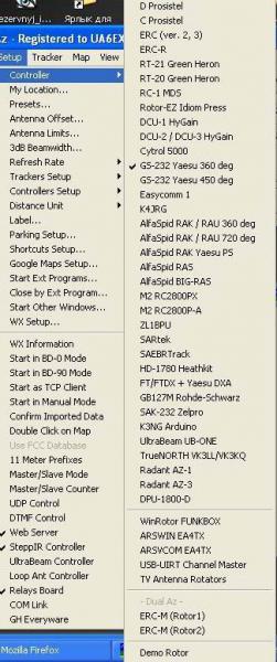
какой такой отладчик? картинка - список поддерживаемых K3NG устройств )))
Дошло)))
Мне не нужны доли градусов, у меня несколько иные потребности))) Не для УКВ это)))
После довольно длительного "молчания" в эфире восстанавливаю своё хозяйство, пока по мачтам лазить не хочется, пересматриваю аппаратную часть, вернее- автоматизацию "промежуточных процессов"))))- антенные коммутаторы, бэнд-декодеры и т.п. Выбор пал на ардуино. Где-то нано, где-то микро, благо купить их у китайцев- сущие гроши, да и паять почти не надо. Посмотрел на GS-232, мне там, в принципе, особо много и не надо, поэтому написать особого труда не составит.
В добрый путь!
Кстати программа PSTROTATOR для этих целей хороша
Да, Виктор, всё понятно. Всё получилось без особых проблем. Осталось "расчесать" прошивку и повысить устойчивость к всякого рода наводкам. Я не любитель QRP))) Если коротко, то собирается такой вариант: 4 кнопки для каких-то азимутов, которые надо запомнить. Короткое нажатие- крутим туда, длинное- запоминаем текущее и очень длинное- калибровки. 5-я кнопка- разворот на LP. индикация- пока LCD 1602- верхняя строка- текущий азимут, нижняя- запомненные. Кроме того, три больших 7-ми сегментника с регистрами. Еще, наверное, прилеплю "циферблат" на каком-нибудь шаговике от принтера. Для экономии ног шина данных LCD-ки и 4 кнопки на одних выводах. Ну, и GS-232. Датчик- резюк проволочный 10 ком. Многооборотник, 10 об. С датчиком пока топчусь на месте) Думаю подать на него 24В, а низу какой-нибудь нормирующий усилитель на ОУ.
Про PST я в курсе)))
А я получил P3022-V1-CW360 они без мёртвой точки, пару преобразователей вверх прямо на поворотке и там выставить +5 вольт, внизу будем иметь 0-5 вольт в зависимости от угла. Перепробовал всё! Многооборотные не могу, надо кинематику переделывать, нет места...чуть затормозилось...субботники-воскресники...пинаю ногами...из анекдота, короче отчёты делаю по работе
Скетчем поделишься? У меня с программированием не айс )))
Без проблем, немного осталось "допилить", но, как всегда, то лень, то некогда)))
А что на КВ городишь? У меня в планах по весне восстановить свою 4-5-6 (11 метров Бум) на 20-15-10 (вороны с грачами 5 элементов поломали, концы были совсем тонкостенные), собрать 3-4 (7 метров бум) на 18-14- уже все давно напилено-размечено. А потом, если получится, заняться УКВ антеннами. Тут стеки))). Мачта стоит, материалы лежат, сумматоры-делители уже окислиться успели)))
Подниму тему )))