/*!
 * @file RGBmatrixPanel.cpp
 *
 * @mainpage Adafruit RGB Matrix Panel library.
 *
 * @section intro_sec Introduction
 *
 * This is the documentation for Adafruit's RGB LED Matrix Panel library
 * for the Arduino platform.  It is designed to work with 16x32, 32x32 and
 * 32x64 panels.
 *
 * A few notes on the implementation:
 *
 * - To control LED brightness, traditional PWM is eschewed in favor of
 *   Binary Code Modulation (aka Bit Angle Modulation), which operates
 *   through a succession of periods each twice the length of the preceeding
 *   one (rather than a direct linear count a la PWM).
 *   <a href="http://www.batsocks.co.uk/readme/art_bcm_1.htm">It's explained
 *   well here.</a>
 *   I was initially skeptical, but it works exceedingly well in practice!
 *   And this uses considerably fewer CPU cycles than software PWM.
 *
 * - Although many control pins are software-configurable in the user's
 *   code, a couple things are tied to specific PORT registers.  It's just
 *   a lot faster this way -- port lookups take time.  Please see the notes
 *   later regarding wiring on "alternative" Arduino boards.
 *
 * - A tiny bit of inline assembly language is used in the most speed-
 *   critical section.  The C++ compiler wasn't making optimal use of the
 *   instruction set in what seemed like an obvious chunk of code.  Since
 *   it's only a few short instructions, this loop is also "unrolled" --
 *   each iteration is stated explicitly, not through a control loop.
 *
 * - The library is stuck with some decisions that were made in the heyday
 *   of 2K RAM AVR microcontrollers. For newer projects on SAMD, ESP32 and
 *   other 32-bit devices, consider using
 *   <a
 * href="https://github.com/adafruit/Adafruit_Protomatter">Adafruit_Protomatter</a>
 *   instead, which offers more flexible support of size and color depth.
 *
 * Adafruit invests time and resources providing this open source code,
 * please support Adafruit and open-source hardware by purchasing
 * products from Adafruit!
 *
 * @section dependencies Dependencies
 *
 * This library depends on <a
 * href="https://github.com/adafruit/Adafruit-GFX-Library"> Adafruit_GFX</a>
 * being present on your system. Please make sure you have installed the latest
 * version before using this library.
 *
 * @section author Author
 *
 * Written by Limor Fried/Ladyada & Phil Burgess/PaintYourDragon for
 * Adafruit Industries.
 *
 * @section license License
 *
 * BSD license, all text here must be included in any redistribution.
 *
 */

#include "RGBmatrixPanel.h"
#include "gamma.h"

#ifdef ARDUINO_ARCH_ESP32
#include "driver/timer.h"
#include "freertos/FreeRTOS.h"
#include <string.h>
#endif

#ifndef _swap_int16_t
#define _swap_int16_t(a, b)                                                    \
  {                                                                            \
    int16_t t = a;                                                             \
    a = b;                                                                     \
    b = t;                                                                     \
  } ///< 16-bit var swap
#endif

// A full PORT register is required for the data lines, though only the
// top 6 output bits are used.  For performance reasons, the port # cannot
// be changed via library calls, only by changing constants in the library.
// For similar reasons, the clock pin is only semi-configurable...it can
// be specified as any pin within a specific PORT register stated below.

/*#if defined(__AVR_ATmega1280__) || defined(__AVR_ATmega2560__)
// Arduino Mega is now tested and confirmed, with the following caveats:
// Because digital pins 2-7 don't map to a contiguous port register,
// the Mega requires connecting the matrix data lines to different pins.
// Digital pins 24-29 are used for the data interface, and 22 & 23 are
// unavailable for other outputs because the software needs to write to
// the full PORTA register for speed.  Clock may be any pin on PORTB --
// on the Mega, this CAN'T be pins 8 or 9 (these are on PORTH), thus the
// wiring will need to be slightly different than the tutorial's
// explanation on the Uno, etc.  Pins 10-13 are all fair game for the
// clock, as are pins 50-53.
#define DATAPORT PORTA ///< RGB data PORT register
#define DATADIR DDRA   ///< RGB data direction register
#define CLKPORT PORTB  ///< RGB clock PORT register
#elif defined(__AVR_ATmega32U4__)
// Arduino Leonardo: this is vestigial code an unlikely to ever be
// finished -- DO NOT USE!!!  Unlike the Uno, digital pins 2-7 do NOT
// map to a contiguous port register, dashing our hopes for compatible
// wiring.  Making this work would require significant changes both to
// the bit-shifting code in the library, and how this board is wired to
// the LED matrix.  Bummer.
#define DATAPORT PORTD ///< RGB data PORT register
#define DATADIR DDRD   ///< RGB data direction register
#define CLKPORT PORTB  ///< RGB clock PORT register
#elif defined(ARDUINO_ARCH_SAMD) || defined(ARDUINO_ARCH_ESP32)
// Support for ATSAMD21-based boards, done with PortType!
#else
// Ports for "standard" boards (Arduino Uno, Duemilanove, etc.)
#define DATAPORT PORTD ///< RGB data PORT register
#define DATADIR DDRD   ///< RGB data direction register
#define CLKPORT PORTB  ///< RGB clock PORT register
#endif
*/
// Ports for atmega1284
#define DATAPORT PORTD ///< RGB data PORT register
#define DATADIR DDRD   ///< RGB data direction register
#define CLKPORT PORTB  ///< RGB clock PORT register

#define nPlanes 4 ///< Bit depth per R,G,B (4 = (2^4)^3 = 4096 colors)

// The fact that the display driver interrupt stuff is tied to the
// singular Timer1 doesn't really take well to object orientation with
// multiple RGBmatrixPanel instances.  The solution at present is to
// allow instances, but only one is active at any given time, via its
// begin() method.  The implementation is still incomplete in parts;
// the prior active panel really should be gracefully disabled, and a
// stop() method should perhaps be added...assuming multiple instances
// are even an actual need.
static RGBmatrixPanel *activePanel = NULL; ///< Active RGB panel object

// Code common to both the 16x32 and 32x32 constructors:
void RGBmatrixPanel::init(uint8_t rows, uint8_t a, uint8_t b, uint8_t c,
                          uint8_t clk, uint8_t lat, uint8_t oe, boolean dbuf,
                          uint8_t width
#if defined(ARDUINO_ARCH_SAMD) || defined(ARDUINO_ARCH_ESP32)
                          ,
                          uint8_t *pinlist
#endif
) {
#if defined(ARDUINO_ARCH_SAMD) || defined(ARDUINO_ARCH_ESP32)
  // R1, G1, B1, R2, G2, B2 pins
  static const uint8_t defaultrgbpins[] = {2, 3, 4, 5, 6, 7};
  memcpy(rgbpins, pinlist ? pinlist : defaultrgbpins, sizeof rgbpins);
#if defined(ARDUINO_ARCH_SAMD)
  // All six RGB pins MUST be on the same PORT # as CLK
  int clkportnum = g_APinDescription[clk].ulPort;
  for (uint8_t i = 0; i < 6; i++) {
    if (g_APinDescription[rgbpins[i]].ulPort != clkportnum)
      return;
  }
#endif
#endif

  nRows = rows; // Number of multiplexed rows; actual height is 2X this

  // Allocate and initialize matrix buffer:
  int buffsize = width * nRows * 3, // x3 = 3 bytes holds 4 planes "packed"
      allocsize = (dbuf == true) ? (buffsize * 2) : buffsize;
  if (NULL == (matrixbuff[0] = (uint8_t *)malloc(allocsize)))
    return;
  memset(matrixbuff[0], 0, allocsize);
  // If not double-buffered, both buffers then point to the same address:
  matrixbuff[1] = (dbuf == true) ? &matrixbuff[0][buffsize] : matrixbuff[0];

  // Save pin numbers for use by begin() method later.
  _a = a;
  _b = b;
  _c = c;
  _clk = clk;
  _lat = lat;
  _oe = oe;

  // Look up port registers and pin masks ahead of time,
  // avoids many slow digitalWrite() calls later.
  clkmask = digitalPinToBitMask(clk);
  latport = portOutputRegister(digitalPinToPort(lat));
  latmask = digitalPinToBitMask(lat);
  oeport = portOutputRegister(digitalPinToPort(oe));
  oemask = digitalPinToBitMask(oe);
  addraport = portOutputRegister(digitalPinToPort(a));
  addramask = digitalPinToBitMask(a);
  addrbport = portOutputRegister(digitalPinToPort(b));
  addrbmask = digitalPinToBitMask(b);
  addrcport = portOutputRegister(digitalPinToPort(c));
  addrcmask = digitalPinToBitMask(c);
  plane = nPlanes - 1;
  row = nRows - 1;
  swapflag = false;
  backindex = 0; // Array index of back buffer
}

// Constructor for 16x32 panel:
RGBmatrixPanel::RGBmatrixPanel(uint8_t a, uint8_t b, uint8_t c, uint8_t clk,
                               uint8_t lat, uint8_t oe, boolean dbuf
#if defined(ARDUINO_ARCH_SAMD) || defined(ARDUINO_ARCH_ESP32)
                               ,
                               uint8_t *pinlist
#endif
                               )
    : Adafruit_GFX(32, 16) {
  init(8, a, b, c, clk, lat, oe, dbuf, 32
#if defined(ARDUINO_ARCH_SAMD) || defined(ARDUINO_ARCH_ESP32)
       ,
       pinlist
#endif
  );
}

// Constructor for 32x32 or 32x64 panel:
RGBmatrixPanel::RGBmatrixPanel(uint8_t a, uint8_t b, uint8_t c, uint8_t d,
                               uint8_t clk, uint8_t lat, uint8_t oe,
                               boolean dbuf, uint8_t width
#if defined(ARDUINO_ARCH_SAMD) || defined(ARDUINO_ARCH_ESP32)
                               ,
                               uint8_t *pinlist
#endif
                               )
    : Adafruit_GFX(width, 32) {

  init(16, a, b, c, clk, lat, oe, dbuf, width
#if defined(ARDUINO_ARCH_SAMD) || defined(ARDUINO_ARCH_ESP32)
       ,
       pinlist
#endif
  );

  // Init a few extra 32x32-specific elements:
  _d = d;
  addrdport = portOutputRegister(digitalPinToPort(d));
  addrdmask = digitalPinToBitMask(d);
}

#if defined(ARDUINO_ARCH_SAMD)
#define TIMER TC4
#define IRQN TC4_IRQn
#define IRQ_HANDLER TC4_Handler
#define TIMER_GCLK_ID TC4_GCLK_ID
#elif defined(ARDUINO_ARCH_ESP32)
IRAM_ATTR void IRQ_HANDLER(void *);
#endif

void RGBmatrixPanel::begin(void) {

  backindex = 0;                       // Back buffer
  buffptr = matrixbuff[1 - backindex]; // -> front buffer
  activePanel = this;                  // For interrupt hander

  // Enable all comm & address pins as outputs, set default states:
  pinMode(_clk, OUTPUT);
  digitalWrite(_clk, LOW); // Low
  pinMode(_lat, OUTPUT);
  *latport &= ~latmask; // Low
  pinMode(_oe, OUTPUT);
  *oeport |= oemask; // High (disable output)
  pinMode(_a, OUTPUT);
  *addraport &= ~addramask; // Low
  pinMode(_b, OUTPUT);
  *addrbport &= ~addrbmask; // Low
  pinMode(_c, OUTPUT);
  *addrcport &= ~addrcmask; // Low
  if (nRows > 8) {
    pinMode(_d, OUTPUT);
    *addrdport &= ~addrdmask; // Low
  }

#if defined(__AVR__)

  // The high six bits of the data port are set as outputs;
  // Might make this configurable in the future, but not yet.
  DATADIR = B11111100;
  DATAPORT = 0;

#elif defined(ARDUINO_ARCH_SAMD)

  // Semi-configurable RGB bits; must be on same PORT as CLK
  int clkportnum = g_APinDescription[_clk].ulPort;
#ifdef __SAMD51__ // No IOBUS on SAMD51
  outsetreg = &(PORT->Group[clkportnum].OUTSET.reg);
  outclrreg = &(PORT->Group[clkportnum].OUTCLR.reg);
#else
  outsetreg = &(PORT_IOBUS->Group[clkportnum].OUTSET.reg);
  outclrreg = &(PORT_IOBUS->Group[clkportnum].OUTCLR.reg);
#endif

  PortType rgbmask[6];
  clkmask = rgbclkmask = digitalPinToBitMask(_clk);
  for (uint8_t i = 0; i < 6; i++) {
    pinMode(rgbpins[i], OUTPUT);
    rgbmask[i] = digitalPinToBitMask(rgbpins[i]); // Pin bit mask
    rgbclkmask |= rgbmask[i];                     // Add to RGB+CLK bit mask
  }
  for (int i = 0; i < 256; i++) {
    expand[i] = 0;
    if (i & 0x04)
      expand[i] |= rgbmask[0];
    if (i & 0x08)
      expand[i] |= rgbmask[1];
    if (i & 0x10)
      expand[i] |= rgbmask[2];
    if (i & 0x20)
      expand[i] |= rgbmask[3];
    if (i & 0x40)
      expand[i] |= rgbmask[4];
    if (i & 0x80)
      expand[i] |= rgbmask[5];
  }
#elif defined(ARDUINO_ARCH_ESP32)
  // Semi-configurable RGB bits; must be on same PORT as CLK
  if (_clk < 32) {
    outsetreg = &GPIO.out_w1ts;
    outclrreg = &GPIO.out_w1tc;
  } else {
    outsetreg = (volatile PortType *)&(GPIO.out1_w1ts);
    outclrreg = (volatile PortType *)&(GPIO.out1_w1tc);
  }

  PortType rgbmask[6];
  clkmask = rgbclkmask = digitalPinToBitMask(_clk);
  for (uint8_t i = 0; i < 6; i++) {
    pinMode(rgbpins[i], OUTPUT);
    rgbmask[i] = digitalPinToBitMask(rgbpins[i]); // Pin bit mask
    rgbclkmask |= rgbmask[i];                     // Add to RGB+CLK bit mask
  }
  for (int i = 0; i < 256; i++) {
    expand[i] = 0;
    if (i & 0x04)
      expand[i] |= rgbmask[0];
    if (i & 0x08)
      expand[i] |= rgbmask[1];
    if (i & 0x10)
      expand[i] |= rgbmask[2];
    if (i & 0x20)
      expand[i] |= rgbmask[3];
    if (i & 0x40)
      expand[i] |= rgbmask[4];
    if (i & 0x80)
      expand[i] |= rgbmask[5];
  }
#endif

#if defined(ARDUINO_ARCH_ESP32)
  timer_config_t tim_config;
  tim_config.divider = 2; // Run Timer at 40 MHz
  tim_config.counter_dir = TIMER_COUNT_UP;
  tim_config.counter_en = TIMER_PAUSE;
  tim_config.alarm_en = TIMER_ALARM_EN;
  tim_config.auto_reload = TIMER_AUTORELOAD_EN;
  tim_config.intr_type = TIMER_INTR_LEVEL;

  timer_init(TIMER_GROUP_1, TIMER_0, &tim_config);
  /* Timer's counter will initially start from value below.
       Also, if auto_reload is set, this value will be automatically reload on
     alarm */
  timer_set_counter_value(TIMER_GROUP_1, TIMER_0, 0x00000000ULL);
  /* Configure the alarm value and the interrupt on alarm. */
  timer_set_alarm_value(TIMER_GROUP_1, TIMER_0, 10000);
  timer_enable_intr(TIMER_GROUP_1, TIMER_0);
  timer_isr_register(TIMER_GROUP_1, TIMER_0, IRQ_HANDLER, (void *)TIMER_0,
                     ESP_INTR_FLAG_IRAM, NULL);

  timer_start(TIMER_GROUP_1, TIMER_0);
#endif

#if defined(__AVR__)
  // Set up Timer1 for interrupt:
  TCCR1A = _BV(WGM11);                          // Mode 14 (fast PWM), OC1A off
  TCCR1B = _BV(WGM13) | _BV(WGM12) | _BV(CS10); // Mode 14, no prescale
  ICR1 = 100;
  TIMSK1 |= _BV(TOIE1); // Enable Timer1 interrupt
  sei();                // Enable global interrupts
#endif

#if defined(ARDUINO_ARCH_SAMD)
#ifdef __SAMD51__
  // Set up generic clock gen 2 as source for TC4
  // Datasheet recommends setting GENCTRL register in a single write,
  // so a temp value is used here to more easily construct a value.
  GCLK_GENCTRL_Type genctrl;
  genctrl.bit.SRC = GCLK_GENCTRL_SRC_DFLL_Val; // 48 MHz source
  genctrl.bit.GENEN = 1;                       // Enable
  genctrl.bit.OE = 1;
  genctrl.bit.DIVSEL = 0; // Do not divide clock source
  genctrl.bit.DIV = 0;
  GCLK->GENCTRL[2].reg = genctrl.reg;
  while (GCLK->SYNCBUSY.bit.GENCTRL1 == 1)
    ;

  GCLK->PCHCTRL[TIMER_GCLK_ID].bit.CHEN = 0;
  while (GCLK->PCHCTRL[TIMER_GCLK_ID].bit.CHEN)
    ; // Wait for disable
  GCLK_PCHCTRL_Type pchctrl;
  pchctrl.bit.GEN = GCLK_PCHCTRL_GEN_GCLK2_Val;
  pchctrl.bit.CHEN = 1;
  GCLK->PCHCTRL[TIMER_GCLK_ID].reg = pchctrl.reg;
  while (!GCLK->PCHCTRL[TIMER_GCLK_ID].bit.CHEN)
    ; // Wait for enable

  // Counter must first be disabled to configure it
  TIMER->COUNT16.CTRLA.reg &= ~TC_CTRLA_ENABLE;
  while (TIMER->COUNT16.SYNCBUSY.bit.STATUS)
    ;

  TIMER->COUNT16.CTRLA.reg =    // Configure timer counter
      TC_CTRLA_PRESCALER_DIV1 | // 1:1 Prescale
      TC_CTRLA_MODE_COUNT16;    // 16-bit counter mode

  TIMER->COUNT16.WAVE.bit.WAVEGEN = 1; // Match frequency mode (MFRQ)

  TIMER->COUNT16.CTRLBSET.reg = TCC_CTRLBCLR_DIR; // Count DOWN
  while (TIMER->COUNT16.SYNCBUSY.bit.CTRLB)
    ;

  TIMER->COUNT16.CC[0].reg = 10000; // Compare value for channel 0
  while (TIMER->COUNT16.SYNCBUSY.bit.CC0)
    ;

  TIMER->COUNT16.INTENSET.reg = TC_INTENSET_OVF; // Enable overflow interrupt

  NVIC_DisableIRQ(IRQN);
  NVIC_ClearPendingIRQ(IRQN);
  NVIC_SetPriority(IRQN, 0); // Top priority
  NVIC_EnableIRQ(IRQN);

  // Enable TCx
  TIMER->COUNT16.CTRLA.reg |= TC_CTRLA_ENABLE;
  while (TIMER->COUNT16.SYNCBUSY.bit.STATUS)
    ;
#else
  // Enable GCLK for TC4 and COUNTER (timer counter input clock)
  GCLK->CLKCTRL.reg = (uint16_t)(GCLK_CLKCTRL_CLKEN | GCLK_CLKCTRL_GEN_GCLK0 |
                                 GCLK_CLKCTRL_ID(GCM_TC4_TC5));
  while (GCLK->STATUS.bit.SYNCBUSY == 1)
    ;

  // Counter must first be disabled to configure it
  TIMER->COUNT16.CTRLA.reg &= ~TC_CTRLA_ENABLE;
  while (TIMER->COUNT16.STATUS.bit.SYNCBUSY)
    ;

  TIMER->COUNT16.CTRLA.reg =    // Configure timer counter
      TC_CTRLA_PRESCALER_DIV1 | // 1:1 Prescale
      TC_CTRLA_WAVEGEN_MFRQ |   // Match frequency generation mode (MFRQ)
      TC_CTRLA_MODE_COUNT16;    // 16-bit counter mode
  while (TIMER->COUNT16.STATUS.bit.SYNCBUSY)
    ;

  //  TIMER->COUNT16.CTRLBCLR.reg = TCC_CTRLBCLR_DIR; // Count up
  TIMER->COUNT16.CTRLBSET.reg = TCC_CTRLBCLR_DIR; // Count DOWN
  while (TIMER->COUNT16.STATUS.bit.SYNCBUSY)
    ;

  TIMER->COUNT16.CC[0].reg = 10000; // Compare value for channel 0
  while (TIMER->COUNT16.STATUS.bit.SYNCBUSY)
    ;

  TIMER->COUNT16.INTENSET.reg = TC_INTENSET_OVF; // Enable overflow interrupt

  NVIC_DisableIRQ(IRQN);
  NVIC_ClearPendingIRQ(IRQN);
  NVIC_SetPriority(IRQN, 0); // Top priority
  NVIC_EnableIRQ(IRQN);

  // Enable TCx
  TIMER->COUNT16.CTRLA.reg |= TC_CTRLA_ENABLE;
  while (TIMER->COUNT16.STATUS.bit.SYNCBUSY)
    ;
#endif // SAMD21
#endif // ARDUINO_ARCH_SAMD
}

// Original RGBmatrixPanel library used 3/3/3 color.  Later version used
// 4/4/4.  Then Adafruit_GFX (core library used across all Adafruit
// display devices now) standardized on 5/6/5.  The matrix still operates
// internally on 4/4/4 color, but all the graphics functions are written
// to expect 5/6/5...the matrix lib will truncate the color components as
// needed when drawing.  These next functions are mostly here for the
// benefit of older code using one of the original color formats.

// Promote 3/3/3 RGB to Adafruit_GFX 5/6/5
uint16_t RGBmatrixPanel::Color333(uint8_t r, uint8_t g, uint8_t b) {
  // RRRrrGGGgggBBBbb
  return ((r & 0x7) << 13) | ((r & 0x6) << 10) | ((g & 0x7) << 8) |
         ((g & 0x7) << 5) | ((b & 0x7) << 2) | ((b & 0x6) >> 1);
}

// Promote 4/4/4 RGB to Adafruit_GFX 5/6/5
uint16_t RGBmatrixPanel::Color444(uint8_t r, uint8_t g, uint8_t b) {
  // RRRRrGGGGggBBBBb
  return ((r & 0xF) << 12) | ((r & 0x8) << 8) | ((g & 0xF) << 7) |
         ((g & 0xC) << 3) | ((b & 0xF) << 1) | ((b & 0x8) >> 3);
}

// Demote 8/8/8 to Adafruit_GFX 5/6/5
// If no gamma flag passed, assume linear color
uint16_t RGBmatrixPanel::Color888(uint8_t r, uint8_t g, uint8_t b) {
  return ((uint16_t)(r & 0xF8) << 8) | ((uint16_t)(g & 0xFC) << 3) | (b >> 3);
}

// 8/8/8 -> gamma -> 5/6/5
uint16_t RGBmatrixPanel::Color888(uint8_t r, uint8_t g, uint8_t b,
                                  boolean gflag) {
  if (gflag) {                          // Gamma-corrected color?
    r = pgm_read_byte(&gamma_table[r]); // Gamma correction table maps
    g = pgm_read_byte(&gamma_table[g]); // 8-bit input to 4-bit output
    b = pgm_read_byte(&gamma_table[b]);
    return ((uint16_t)r << 12) | ((uint16_t)(r & 0x8) << 8) | // 4/4/4->5/6/5
           ((uint16_t)g << 7) | ((uint16_t)(g & 0xC) << 3) | (b << 1) |
           (b >> 3);
  } // else linear (uncorrected) color
  return ((uint16_t)(r & 0xF8) << 8) | ((uint16_t)(g & 0xFC) << 3) | (b >> 3);
}

uint16_t RGBmatrixPanel::ColorHSV(long hue, uint8_t sat, uint8_t val,
                                  boolean gflag) {

  uint8_t r, g, b, lo;
  uint16_t s1, v1;

  // Hue
  hue %= 1536; // -1535 to +1535
  if (hue < 0)
    hue += 1536;      //     0 to +1535
  lo = hue & 255;     // Low byte  = primary/secondary color mix
  switch (hue >> 8) { // High byte = sextant of colorwheel
  case 0:
    r = 255;
    g = lo;
    b = 0;
    break; // R to Y
  case 1:
    r = 255 - lo;
    g = 255;
    b = 0;
    break; // Y to G
  case 2:
    r = 0;
    g = 255;
    b = lo;
    break; // G to C
  case 3:
    r = 0;
    g = 255 - lo;
    b = 255;
    break; // C to B
  case 4:
    r = lo;
    g = 0;
    b = 255;
    break; // B to M
  default:
    r = 255;
    g = 0;
    b = 255 - lo;
    break; // M to R
  }

  // Saturation: add 1 so range is 1 to 256, allowig a quick shift operation
  // on the result rather than a costly divide, while the type upgrade to int
  // avoids repeated type conversions in both directions.
  s1 = sat + 1;
  r = 255 - (((255 - r) * s1) >> 8);
  g = 255 - (((255 - g) * s1) >> 8);
  b = 255 - (((255 - b) * s1) >> 8);

  // Value (brightness) & 16-bit color reduction: similar to above, add 1
  // to allow shifts, and upgrade to int makes other conversions implicit.
  v1 = val + 1;
  if (gflag) { // Gamma-corrected color?
    r = pgm_read_byte(
        &gamma_table[(r * v1) >> 8]); // Gamma correction table maps
    g = pgm_read_byte(
        &gamma_table[(g * v1) >> 8]); // 8-bit input to 4-bit output
    b = pgm_read_byte(&gamma_table[(b * v1) >> 8]);
  } else {              // linear (uncorrected) color
    r = (r * v1) >> 12; // 4-bit results
    g = (g * v1) >> 12;
    b = (b * v1) >> 12;
  }
  return (r << 12) | ((r & 0x8) << 8) | // 4/4/4 -> 5/6/5
         (g << 7) | ((g & 0xC) << 3) | (b << 1) | (b >> 3);
}

void RGBmatrixPanel::drawPixel(int16_t x, int16_t y, uint16_t c) {
  uint8_t r, g, b, bit, limit, *ptr;

  if ((x < 0) || (x >= _width) || (y < 0) || (y >= _height))
    return;

  switch (rotation) {
  case 1:
    _swap_int16_t(x, y);
    x = WIDTH - 1 - x;
    break;
  case 2:
    x = WIDTH - 1 - x;
    y = HEIGHT - 1 - y;
    break;
  case 3:
    _swap_int16_t(x, y);
    y = HEIGHT - 1 - y;
    break;
  }

  // Adafruit_GFX uses 16-bit color in 5/6/5 format, while matrix needs
  // 4/4/4.  Pluck out relevant bits while separating into R,G,B:
  r = c >> 12;        // RRRRrggggggbbbbb
  g = (c >> 7) & 0xF; // rrrrrGGGGggbbbbb
  b = (c >> 1) & 0xF; // rrrrrggggggBBBBb

  // Loop counter stuff
  bit = 2;
  limit = 1 << nPlanes;

  if (y < nRows) {
    // Data for the upper half of the display is stored in the lower
    // bits of each byte.
    ptr = &matrixbuff[backindex][y * WIDTH * (nPlanes - 1) + x]; // Base addr
    // Plane 0 is a tricky case -- its data is spread about,
    // stored in least two bits not used by the other planes.
    ptr[WIDTH * 2] &= ~B00000011; // Plane 0 R,G mask out in one op
    if (r & 1)
      ptr[WIDTH * 2] |= B00000001; // Plane 0 R: 64 bytes ahead, bit 0
    if (g & 1)
      ptr[WIDTH * 2] |= B00000010; // Plane 0 G: 64 bytes ahead, bit 1
    if (b & 1)
      ptr[WIDTH] |= B00000001; // Plane 0 B: 32 bytes ahead, bit 0
    else
      ptr[WIDTH] &= ~B00000001; // Plane 0 B unset; mask out
    // The remaining three image planes are more normal-ish.
    // Data is stored in the high 6 bits so it can be quickly
    // copied to the DATAPORT register w/6 output lines.
    for (; bit < limit; bit <<= 1) {
      *ptr &= ~B00011100; // Mask out R,G,B in one op
      if (r & bit)
        *ptr |= B00000100; // Plane N R: bit 2
      if (g & bit)
        *ptr |= B00001000; // Plane N G: bit 3
      if (b & bit)
        *ptr |= B00010000; // Plane N B: bit 4
      ptr += WIDTH;        // Advance to next bit plane
    }
  } else {
    // Data for the lower half of the display is stored in the upper
    // bits, except for the plane 0 stuff, using 2 least bits.
    ptr = &matrixbuff[backindex][(y - nRows) * WIDTH * (nPlanes - 1) + x];
    *ptr &= ~B00000011; // Plane 0 G,B mask out in one op
    if (r & 1)
      ptr[WIDTH] |= B00000010; // Plane 0 R: 32 bytes ahead, bit 1
    else
      ptr[WIDTH] &= ~B00000010; // Plane 0 R unset; mask out
    if (g & 1)
      *ptr |= B00000001; // Plane 0 G: bit 0
    if (b & 1)
      *ptr |= B00000010; // Plane 0 B: bit 0
    for (; bit < limit; bit <<= 1) {
      *ptr &= ~B11100000; // Mask out R,G,B in one op
      if (r & bit)
        *ptr |= B00100000; // Plane N R: bit 5
      if (g & bit)
        *ptr |= B01000000; // Plane N G: bit 6
      if (b & bit)
        *ptr |= B10000000; // Plane N B: bit 7
      ptr += WIDTH;        // Advance to next bit plane
    }
  }
}

void RGBmatrixPanel::fillScreen(uint16_t c) {
  if ((c == 0x0000) || (c == 0xffff)) {
    // For black or white, all bits in frame buffer will be identically
    // set or unset (regardless of weird bit packing), so it's OK to just
    // quickly memset the whole thing:
    memset(matrixbuff[backindex], c, WIDTH * nRows * 3);
  } else {
    // Otherwise, need to handle it the long way:
    Adafruit_GFX::fillScreen(c);
  }
}

// Return address of back buffer -- can then load/store data directly
uint8_t *RGBmatrixPanel::backBuffer() { return matrixbuff[backindex]; }

// For smooth animation -- drawing always takes place in the "back" buffer;
// this method pushes it to the "front" for display.  Passing "true", the
// updated display contents are then copied to the new back buffer and can
// be incrementally modified.  If "false", the back buffer then contains
// the old front buffer contents -- your code can either clear this or
// draw over every pixel.  (No effect if double-buffering is not enabled.)
void RGBmatrixPanel::swapBuffers(boolean copy) {
  if (matrixbuff[0] != matrixbuff[1]) {
    // To avoid 'tearing' display, actual swap takes place in the interrupt
    // handler, at the end of a complete screen refresh cycle.
    swapflag = true; // Set flag here, then...
    while (swapflag == true)
      delay(1); // wait for interrupt to clear it
    if (copy == true)
      memcpy(matrixbuff[backindex], matrixbuff[1 - backindex],
             WIDTH * nRows * 3);
  }
}

// Dump display contents to the Serial Monitor, adding some formatting to
// simplify copy-and-paste of data as a PROGMEM-embedded image for another
// sketch.  If using multiple dumps this way, you'll need to edit the
// output to change the 'img' name for each.  Data can then be loaded
// back into the display using a pgm_read_byte() loop.
void RGBmatrixPanel::dumpMatrix(void) {

  int i, buffsize = WIDTH * nRows * 3;

  Serial.print(F("\n\n"
                 "#include <avr/pgmspace.h>\n\n"
                 "static const uint8_t PROGMEM img[] = {\n  "));

  for (i = 0; i < buffsize; i++) {
    Serial.print(F("0x"));
    if (matrixbuff[backindex][i] < 0x10)
      Serial.write('0');
    Serial.print(matrixbuff[backindex][i], HEX);
    if (i < (buffsize - 1)) {
      if ((i & 7) == 7)
        Serial.print(F(",\n  "));
      else
        Serial.write(',');
    }
  }
  Serial.println(F("\n};"));
}

// -------------------- Interrupt handler stuff --------------------

#if defined(__AVR__)

ISR(TIMER1_OVF_vect, ISR_BLOCK) { // ISR_BLOCK important -- see notes later
  activePanel->updateDisplay();   // Call refresh func for active display
  TIFR1 |= TOV1;                  // Clear Timer1 interrupt flag
}

#elif defined(ARDUINO_ARCH_SAMD)

void IRQ_HANDLER() {
  activePanel->updateDisplay(); // Call refresh func for active display
  TIMER->COUNT16.INTFLAG.reg = TC_INTFLAG_OVF; // Clear overflow flag
}

#elif defined(ARDUINO_ARCH_ESP32)
IRAM_ATTR void IRQ_HANDLER(void *arg) {
  int timer_idx = (int)arg;
  /* Retrieve the interrupt status and the counter value
           from the timer that reported the interrupt */
  uint32_t intr_status = TIMERG1.int_st_timers.val;
  activePanel->updateDisplay(); // Call refresh func for active display
  /* Clear the interrupt
                   and update the alarm time for the timer with without reload
   */
  if ((intr_status & BIT(timer_idx)) && timer_idx == TIMER_0) {
    TIMERG1.int_clr_timers.t0 = 1;
  }
  /* After the alarm has been triggered
   we need enable it again, so it is triggered the next time */
  TIMERG1.hw_timer[timer_idx].config.alarm_en = TIMER_ALARM_EN;
}

#endif

// Two constants are used in timing each successive BCM interval.
// These were found empirically, by checking the value of TCNT1 at
// certain positions in the interrupt code.
// CALLOVERHEAD is the number of CPU 'ticks' from the timer overflow
// condition (triggering the interrupt) to the first line in the
// updateDisplay() method.  It's then assumed (maybe not entirely 100%
// accurately, but close enough) that a similar amount of time will be
// needed at the opposite end, restoring regular program flow.
// LOOPTIME is the number of 'ticks' spent inside the shortest data-
// issuing loop (not actually a 'loop' because it's unrolled, but eh).
// Both numbers are rounded up slightly to allow a little wiggle room
// should different compilers produce slightly different results.
#if defined(__AVR__)
#define CALLOVERHEAD 60 // Actual value measured = 56
#define LOOPTIME 200    // Actual value measured = 188
#endif
#if defined(ARDUINO_ARCH_SAMD)
#define CALLOVERHEAD 60 // Actual = 58
#define LOOPTIME 600    // Actual = 558
#endif
#if defined(ARDUINO_ARCH_ESP32)
#define CALLOVERHEAD 30 // Actual = 25
#define LOOPTIME 400    // Actual = 1563 / 4
#endif
// The "on" time for bitplane 0 (with the shortest BCM interval) can
// then be estimated as LOOPTIME + CALLOVERHEAD * 2.  Each successive
// bitplane then doubles the prior amount of time.  We can then
// estimate refresh rates from this:
// 4 bitplanes = 320 + 640 + 1280 + 2560 = 4800 ticks per row.
// 4800 ticks * 16 rows (for 32x32 matrix) = 76800 ticks/frame.
// 16M CPU ticks/sec / 76800 ticks/frame = 208.33 Hz.
// Actual frame rate will be slightly less due to work being done
// during the brief "LEDs off" interval...it's reasonable to say
// "about 200 Hz."  The 16x32 matrix only has to scan half as many
// rows...so we could either double the refresh rate (keeping the CPU
// load the same), or keep the same refresh rate but halve the CPU
// load.  We opted for the latter.
// Can also estimate CPU use: bitplanes 1-3 all use 320 ticks to
// issue data (the increasing gaps in the timing invervals are then
// available to other code), and bitplane 0 takes 920 ticks out of
// the 2560 tick interval.
// 320 * 3 + 920 = 1880 ticks spent in interrupt code, per row.
// From prior calculations, about 4800 ticks happen per row.
// CPU use = 1880 / 4800 = ~39% (actual use will be very slightly
// higher, again due to code used in the LEDs off interval).
// 16x32 matrix uses about half that CPU load.  CPU time could be
// further adjusted by padding the LOOPTIME value, but refresh rates
// will decrease proportionally, and 200 Hz is a decent target.

// The flow of the interrupt can be awkward to grasp, because data is
// being issued to the LED matrix for the *next* bitplane and/or row
// while the *current* plane/row is being shown.  As a result, the
// counter variables change between past/present/future tense in mid-
// function...hopefully tenses are sufficiently commented.
#if defined(ARDUINO_ARCH_ESP32)
IRAM_ATTR void RGBmatrixPanel::updateDisplay(void) {
#else
void RGBmatrixPanel::updateDisplay(void) {
#endif
  uint8_t i, tick, tock, *ptr;
  uint16_t t, duration;

  *oeport |= oemask;   // Disable LED output during row/plane switchover
  *latport |= latmask; // Latch data loaded during *prior* interrupt

  // Calculate time to next interrupt BEFORE incrementing plane #.
  // This is because duration is the display time for the data loaded
  // on the PRIOR interrupt.  CALLOVERHEAD is subtracted from the
  // result because that time is implicit between the timer overflow
  // (interrupt triggered) and the initial LEDs-off line at the start
  // of this method.
  t = (nRows > 8) ? LOOPTIME : (LOOPTIME * 2);
  duration = ((t + CALLOVERHEAD * 2) << plane) - CALLOVERHEAD;

  // Borrowing a technique here from Ray's Logic:
  // www.rayslogic.com/propeller/Programming/AdafruitRGB/AdafruitRGB.htm
  // This code cycles through all four planes for each scanline before
  // advancing to the next line.  While it might seem beneficial to
  // advance lines every time and interleave the planes to reduce
  // vertical scanning artifacts, in practice with this panel it causes
  // a green 'ghosting' effect on black pixels, a much worse artifact.

  if (++plane >= nPlanes) {   // Advance plane counter.  Maxed out?
    plane = 0;                // Yes, reset to plane 0, and
    if (++row >= nRows) {     // advance row counter.  Maxed out?
      row = 0;                // Yes, reset row counter, then...
      if (swapflag == true) { // Swap front/back buffers if requested
        backindex = 1 - backindex;
        swapflag = false;
      }
      buffptr = matrixbuff[1 - backindex]; // Reset into front buffer
    }
  } else if (plane == 1) {
    // Plane 0 was loaded on prior interrupt invocation and is about to
    // latch now, so update the row address lines before we do that:
    if (row & 0x1)
      *addraport |= addramask;
    else
      *addraport &= ~addramask;
    // MYSTERY: certain matrices REQUIRE these delays ???
    delayMicroseconds(10);
    if (row & 0x2)
      *addrbport |= addrbmask;
    else
      *addrbport &= ~addrbmask;
    delayMicroseconds(10);
    if (row & 0x4)
      *addrcport |= addrcmask;
    else
      *addrcport &= ~addrcmask;
    delayMicroseconds(10);
    if (nRows > 8) {
      if (row & 0x8)
        *addrdport |= addrdmask;
      else
        *addrdport &= ~addrdmask;
      delayMicroseconds(10);
    }
  }

  // buffptr, being 'volatile' type, doesn't take well to optimization.
  // A local register copy can speed some things up:
  ptr = (uint8_t *)buffptr;

#if defined(__AVR__)
  ICR1 = duration; // Set interval for next interrupt
  TCNT1 = 0;       // Restart interrupt timer
#elif defined(ARDUINO_ARCH_SAMD)
#ifdef __SAMD51__
  TIMER->COUNT16.CC[0].reg = duration;
  while (TIMER->COUNT16.SYNCBUSY.bit.CC0)
    ;
  TIMER->COUNT16.COUNT.reg = duration;
  while (TIMER->COUNT16.SYNCBUSY.bit.COUNT)
    ;
#else
  TIMER->COUNT16.CC[0].reg = duration;
  while (TIMER->COUNT16.STATUS.bit.SYNCBUSY)
    ;
  TIMER->COUNT16.COUNT.reg = duration;
  while (TIMER->COUNT16.STATUS.bit.SYNCBUSY)
    ;
#endif // SAMD21
#elif defined(ARDUINO_ARCH_ESP32)
static timg_dev_t *TG[2] = {&TIMERG0, &TIMERG1};
static portMUX_TYPE timer_spinlock[TIMER_GROUP_MAX] = {
    portMUX_INITIALIZER_UNLOCKED, portMUX_INITIALIZER_UNLOCKED};
portENTER_CRITICAL(&timer_spinlock[TIMER_GROUP_1]);
TG[TIMER_GROUP_1]->hw_timer[TIMER_0].alarm_high = 0;
TG[TIMER_GROUP_1]->hw_timer[TIMER_0].alarm_low = (uint32_t)duration;
portEXIT_CRITICAL(&timer_spinlock[TIMER_GROUP_1]);
#endif                  // ARDUINO_ARCH_SAMD
  *oeport &= ~oemask;   // Re-enable output
  *latport &= ~latmask; // Latch down

  // Record current state of CLKPORT register, as well as a second
  // copy with the clock bit set.  This makes the innnermost data-
  // pushing loops faster, as they can just set the PORT state and
  // not have to load/modify/store bits every single time.  It's a
  // somewhat rude trick that ONLY works because the interrupt
  // handler is set ISR_BLOCK, halting any other interrupts that
  // might otherwise also be twiddling the port at the same time
  // (else this would clobber them). only needed for AVR's where you
  // cannot set one bit in a single instruction
#if defined(__AVR__)
  tock = CLKPORT;
  tick = tock | clkmask;
#endif

  if (plane > 0) { // 188 ticks from TCNT1=0 (above) to end of function

    // Planes 1-3 copy bytes directly from RAM to PORT without unpacking.
    // The least 2 bits (used for plane 0 data) are presumed masked out
    // by the port direction bits.

#if defined(__AVR__)
// A tiny bit of inline assembly is used; compiler doesn't pick
// up on opportunity for post-increment addressing mode.
// 5 instruction ticks per 'pew' = 160 ticks total
#define pew                                                                    \
  asm volatile(                                                                \
      "ld  __tmp_reg__, %a[ptr]+"                                              \
      "\n\t"                                                                   \
      "out %[data]    , __tmp_reg__"                                           \
      "\n\t"                                                                   \
      "out %[clk]     , %[tick]"                                               \
      "\n\t"                                                                   \
      "out %[clk]     , %[tock]"                                               \
      "\n" ::[ptr] "e"(ptr),                                                   \
      [data] "I"(_SFR_IO_ADDR(DATAPORT)), [clk] "I"(_SFR_IO_ADDR(CLKPORT)),    \
      [tick] "r"(tick), [tock] "r"(tock));
#elif defined(ARDUINO_ARCH_SAMD) || defined(ARDUINO_ARCH_ESP32)
#ifdef __SAMD51__ // No IOBUS on SAMD51
#define pew                                                                    \
  *outclrreg = rgbclkmask;                                                     \
  *outsetreg = expand[*ptr++];                                                 \
  *outsetreg = clkmask;                                                        \
  asm("nop");
#else
#define pew                                                                    \
  *outclrreg = rgbclkmask;                                                     \
  *outsetreg = expand[*ptr++];                                                 \
  *outsetreg = clkmask;
#endif
#endif

    // Loop is unrolled for speed:
    pew pew pew pew pew pew pew pew pew pew pew pew pew pew pew pew pew pew pew
        pew pew pew pew pew pew pew pew pew pew pew pew pew

        if (WIDTH == 64) {
      pew pew pew pew pew pew pew pew pew pew pew pew pew pew pew pew pew pew
          pew pew pew pew pew pew pew pew pew pew pew pew pew pew
    }

#if defined(ARDUINO_ARCH_SAMD) || defined(ARDUINO_ARCH_ESP32)
    *outclrreg = clkmask; // Set clock low
#endif

    buffptr = ptr; //+= 32;

  } else { // 920 ticks from TCNT1=0 (above) to end of function
#if defined(__AVR__)
    // Planes 1-3 (handled above) formatted their data "in place,"
    // their layout matching that out the output PORT register (where
    // 6 bits correspond to output data lines), maximizing throughput
    // as no conversion or unpacking is needed.  Plane 0 then takes up
    // the slack, with all its data packed into the 2 least bits not
    // used by the other planes.  This works because the unpacking and
    // output for plane 0 is handled while plane 3 is being displayed...
    // because binary coded modulation is used (not PWM), that plane
    // has the longest display interval, so the extra work fits.
    for (i = 0; i < WIDTH; i++) {
      DATAPORT = (ptr[i] << 6) | ((ptr[i + WIDTH] << 4) & 0x30) |
                 ((ptr[i + WIDTH * 2] << 2) & 0x0C);
      CLKPORT = tick; // Clock lo
      CLKPORT = tock; // Clock hi
    }
#elif defined(ARDUINO_ARCH_SAMD) || defined(ARDUINO_ARCH_ESP32)
    for (int i = 0; i < WIDTH; i++) {
      byte b = (ptr[i] << 6) | ((ptr[i + WIDTH] << 4) & 0x30) |
               ((ptr[i + WIDTH * 2] << 2) & 0x0C);

      *outclrreg = rgbclkmask; // Clear all data and clock bits together
      *outsetreg = expand[b];  // Set new data bits
      *outsetreg = clkmask;    // Set clock high
    }
    *outclrreg = clkmask; // Set clock low
#endif
  }
}
может проблема все же в том что чип 1284 а не 1284Р ? я его прикрутил к программматору пикит тоже с выкрутасами - его в списке небыло нашел прогу в ней был файл под него добавил и все пошло! а в IDE -наотказ что юарт1 что юарт2 только без загрузчика! может там сам загрузчик кривой для этого чипа?
может проблема все же в том что чип 1284 а не 1284Р ? я его прикрутил к программматору пикит тоже с выкрутасами - его в списке небыло нашел прогу в ней был файл под него добавил и все пошло! а в IDE -наотказ что юарт1 что юарт2 только без загрузчика! может там сам загрузчик кривой для этого чипа?
zumer67, вы какой то странный... Если хотите помощи, выкладывайте не картинками, где нихрена не видно, а текстом! Фьюзы не поленитесь ручками набрать! Или так ещё долго будете трахаться методом тыка.
мне кажется надо отладить скетч на меге, а уже потом переносить на 1284-ю
на меге никаких проблем вообще нет, это готовая библиотека RGBMatrixPanel, к ней есть примеры.
Она работает, я лично проверял :)
поменял выводы на другие в этом порту - тоже тишина! скорей всего где то косяк с портами в библиотеке.
#elif defined(__AVR_ATmega32U4__) || defined(__AVR_ATmega1284__)
// Arduino Leonardo: this is vestigial code an unlikely to ever be
// finished -- DO NOT USE!!! Unlike the Uno, digital pins 2-7 do NOT
// map to a contiguous port register, dashing our hopes for compatible
// wiring. Making this work would require significant changes both to
// the bit-shifting code in the library, and how this board is wired to
// the LED matrix. Bummer.
#define DATAPORT PORTD ///< RGB data PORT register
#define DATADIR DDRD ///< RGB data direction register
#define CLKPORT PORTB ///< RGB clock PORT register
все же 1284 ближе по портам к ATmega32U4
RGB и ABCD - выводы подают сигналы! CLK LAT OE - тишина!
Я просил вас подтвердить какой-нить ссылкой, что у корпуса TQFN другое соответствие портов МК и контактов ардуино. Где на вашей картинке номера пинов ардуино?
Вообще обычно номера пинов ардуино не зависят от типа коруса МК. Например у атмеги328 что в ДИП корпусе что в SMD порт PВ0 - это пин 12 ардуино.
А просил я показать это потому, что у вас в коде указаны неправильные номера пинов для CLK OE и LAT
я и не утверждал что библиотека с косяком! а что я к ней по косячному отношусь!))) яж с микрочипами только да с стм никак не предпологал что так споткнусь на атмега
Я просил вас подтвердить какой-нить ссылкой, что у корпуса TQFN другое соответствие портов МК и контактов ардуино. Где на вашей картинке номера пинов ардуино?
Вообще обычно номера пинов ардуино не зависят от типа коруса МК. Например у атмеги328 что в ДИП корпусе что в SMD порт PВ0 - это пин 12 ардуино.
А просил я показать это потому, что у вас в коде указаны неправильные номера пинов для CLK OE и LAT
у меня нет платы ардуино - есть своя плата и голый чип - вот я и вяжусь к тому что у меня на корпусе выводы другие
поменял выводы на другие в этом порту - тоже тишина! скорей всего где то косяк с портами в библиотеке.
Извини, но это у тебя в голове большой такой косяк.( Google.
огромное всем спасибо кто не остался равнодушен и смог ткнуть мне пальцем!!!! )))) ну никак не ожидал и не подорзревал что номера выставляются не по номерам чипа!)))
нет никакой стыдобы! на ошибках учатся - некоторые на чужих конечно! взял ардуино только из за готовой библиотеки на матрицу а так бы и дальше на пиках шлепал бы))))
А какие проблемы библиотеку на пик перепереть? В либах редко встречаются настолько железозависимые вещи, что прям ни как. А написать как ардуиновские digitalWrite digitalRead вообще не проблема, после чего куча библиотек прям в мплабе можно пользовать.
мне кажется надо отладить скетч на меге, а уже потом переносить на 1284-ю
на меге никаких проблем вообще нет, это готовая библиотека RGBMatrixPanel, к ней есть примеры.
Она работает, я лично проверял :)
http://wiki.amperka.ru/projects:rgb-led-matrix-arduino
подключение меги к матрице
мне кажется надо отладить скетч на меге, а уже потом переносить на 1284-ю
на меге никаких проблем вообще нет, это готовая библиотека RGBMatrixPanel, к ней есть примеры.
Она работает, я лично проверял :)
у меня тоже работает на меге но мне надо прикрутить к atmel1284
Вот вы пишете, что сейчас подключено такЖ
как подлючены пины сейчас
atmega1284
R1 - 24 - PD2 A - A5 -PA5 -ADC5
G1 - 25 - PD3 B - A4 -PA4 -ADC4
B1 - 26 - PD4 C - A3 -PA3 -ADC3
R2 - 27 - PD5 D - A2 -PA2 -ADC2
G2 - 28 - PD6 CLK - 11 -PB5
B2 - 29 - PD7 LAT - 10 -PB6
OE - 12 -PB7
А в коде у вас так:
и как оно будет работать после этого?
это описка yна плате и в .ino так
CLK - 1 - PB5
OE - 2 - PB6
LAT -3 - PB7
мне кажется не проходит инициализаци порта В или самих пинов они в "0"
я попытался просто подергать этими ножками - тишина
да и это тоже не работает
Ок. идем дальше.
проверьте, чтобы макрос
включал ваш МК 1284
да и это тоже не работает
а через pinMode(REL1, OUTPUT) ?
это описка yна плате и в .ino так
CLK - 1 - PB5
OE - 2 - PB6
LAT -3 - PB7
откуда эти цифры?
вот распиновка атмеги1284 в Ардуино(пины ардуино - в круглых скобках):
да и это тоже не работает
а через pinMode(REL1, OUTPUT) ?
а так весь порт нельзя? DDRC = B11111100; сейчас попробую через Pin mode
собрал вот так! тишина!
int REL1 = 21; int REL2 = 22; int TEST = 24; int K1 = 19; int K2 = 20; int ZUM = 23; int tst1 = 1; int tst2 = 2; int tst3 = 3; void setup() { // put your setup code here, to run once: //DDRA = B11111111; //DDRB = B11111111; //DDRC = B11111111; //DDRD = B11111111; pinMode(REL1, OUTPUT); pinMode(REL2, OUTPUT); pinMode(TEST, OUTPUT); pinMode(ZUM, OUTPUT); } void loop() { // put your main code here, to run repeatedly: //PORTA = B11111111; //PORTB = B11111111; //PORTC = B11111111; //PORTD = B11111111; digitalWrite(REL1, LOW); digitalWrite(REL2, LOW); digitalWrite(TEST, LOW); digitalWrite(ZUM, LOW); delay(250); // wait for a second //PORTA = B00000000; //PORTB = B00000000; //PORTC = B00000000; //PORTD = B00000000; digitalWrite(REL1, HIGH); digitalWrite(REL2, HIGH); digitalWrite(TEST, HIGH); digitalWrite(ZUM, HIGH); delay(250); // wait for a second }возможно что надо в порту С что то отключить?
С портами вам придется разбираться самому. Ищите причину, почему у вас регистры DDRx и PORTx не работают. Тут я через инет ничего не посоветую.
вот не нравится мне, что загрузчик не заливается, вот не нравится
вот не нравится мне, что загрузчик не заливается, вот не нравится
а через AVRDUDESHELL - можно загрузчик поставить?
а так весь порт нельзя? DDRC = B11111100; сейчас попробую через Pin mode
можно и весь порт сразу, такая запись тоже должна работать. Что-то у вас не так с контроллером...
возможно что надо в порту С что то отключить?
jtag
вот не нравится мне, что загрузчик не заливается, вот не нравится
а через AVRDUDESHELL - можно загрузчик поставить?
не, я извращениями не занимаюсь, мне IDE достаточно, если не работает, надо разбираться почему
может проблема все же в том что чип 1284 а не 1284Р ? я его прикрутил к программматору пикит тоже с выкрутасами - его в списке небыло нашел прогу в ней был файл под него добавил и все пошло! а в IDE -наотказ что юарт1 что юарт2 только без загрузчика! может там сам загрузчик кривой для этого чипа?
может проблема все же в том что чип 1284 а не 1284Р ? я его прикрутил к программматору пикит тоже с выкрутасами - его в списке небыло нашел прогу в ней был файл под него добавил и все пошло! а в IDE -наотказ что юарт1 что юарт2 только без загрузчика! может там сам загрузчик кривой для этого чипа?
всё там пучком!
zumer67, вы какой то странный... Если хотите помощи, выкладывайте не картинками, где нихрена не видно, а текстом! Фьюзы не поленитесь ручками набрать! Или так ещё долго будете трахаться методом тыка.
jtag
помогло! порт С начал работать!
Ок. идем дальше.
проверьте, чтобы макрос
включал ваш МК 1284
ругается компилятор! #ifndef _AVR_ATmega1284
и вопрос - так все делают - правят файл .сср в редактора ?
такой вариант прокатил!
проршел вариант с __AVR_ATmega1284__
что за поток сознания?
у меня корпус TQFP 44 там распиновка другая
это описка yна плате и в .ino так
CLK - 1 - PB5
OE - 2 - PB6
LAT -3 - PB7
откуда эти цифры?
вот распиновка атмеги1284 в Ардуино(пины ардуино - в круглых скобках):
TQFP 44 распиновка другая
мне кажется надо отладить скетч на меге, а уже потом переносить на 1284-ю
на меге никаких проблем вообще нет, это готовая библиотека RGBMatrixPanel, к ней есть примеры.
Она работает, я лично проверял :)
поменял выводы на другие в этом порту - тоже тишина! скорей всего где то косяк с портами в библиотеке.
все же 1284 ближе по портам к ATmega32U4
RGB и ABCD - выводы подают сигналы! CLK LAT OE - тишина!
TQFP 44 распиновка другая
Корпус другой, а распиновка та же.
Если нет - дайте ссылку, где описана эта "другая" распиновка?
http://ww1.microchip.com/downloads/en/devicedoc/atmel-42718-atmega1284_d... TQFN
TQFN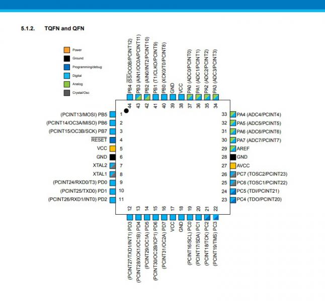
zumer67, вы не поняли.... это мне не нужно.
Я просил вас подтвердить какой-нить ссылкой, что у корпуса TQFN другое соответствие портов МК и контактов ардуино. Где на вашей картинке номера пинов ардуино?
Вообще обычно номера пинов ардуино не зависят от типа коруса МК. Например у атмеги328 что в ДИП корпусе что в SMD порт PВ0 - это пин 12 ардуино.
А просил я показать это потому, что у вас в коде указаны неправильные номера пинов для CLK OE и LAT
поменял выводы на другие в этом порту - тоже тишина! скорей всего где то косяк с портами в библиотеке.
Извини, но это у тебя в голове большой такой косяк.(
Google.
я и не утверждал что библиотека с косяком! а что я к ней по косячному отношусь!))) яж с микрочипами только да с стм никак не предпологал что так споткнусь на атмега
zumer67, вы не поняли.... это мне не нужно.
Я просил вас подтвердить какой-нить ссылкой, что у корпуса TQFN другое соответствие портов МК и контактов ардуино. Где на вашей картинке номера пинов ардуино?
Вообще обычно номера пинов ардуино не зависят от типа коруса МК. Например у атмеги328 что в ДИП корпусе что в SMD порт PВ0 - это пин 12 ардуино.
А просил я показать это потому, что у вас в коде указаны неправильные номера пинов для CLK OE и LAT
у меня нет платы ардуино - есть своя плата и голый чип - вот я и вяжусь к тому что у меня на корпусе выводы другие
поменял выводы на другие в этом порту - тоже тишина! скорей всего где то косяк с портами в библиотеке.
Извини, но это у тебя в голове большой такой косяк.(
Google.
огромное всем спасибо кто не остался равнодушен и смог ткнуть мне пальцем!!!! )))) ну никак не ожидал и не подорзревал что номера выставляются не по номерам чипа!)))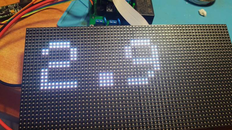
ну и молодец.
Надо будет что-то более серьезное на подобных матрицах - обрашайся. работаю с ними на стм32
ну никак не ожидал и не подорзревал что номера выставляются не по номерам чипа!)))
Вообще-то элементарные рассуждения приводят к мысли, что номера Ардуино никак не могут совпадать с "номерами чипа".
ну никак не ожидал и не подорзревал что номера выставляются не по номерам чипа!)))
Вообще-то элементарные рассуждения приводят к мысли, что номера Ардуино никак не могут совпадать с "номерами чипа".
я в начале писал что работаю в основном с pic а в MPLAB операции с выходами и входами идут по названию портов и битов портов а не выходами плат! )))
ну и молодец.
Надо будет что-то более серьезное на подобных матрицах - обрашайся. работаю с ними на стм32
ок если что буду обращатся!
я в начале писал что работаю в основном с pic а в MPLAB операции с выходами и входами идут по названию портов и битов портов а не выходами плат! )))
это ардуино! если пин имеет и цифровое и аналоговое обозначение то обращаться можно по любому из обозначений
я в начале писал что работаю в основном с pic а в MPLAB операции с выходами и входами идут по названию портов и битов портов а не выходами плат! )))
это ардуино! если пин имеет и цифровое и аналоговое обозначение то обращаться можно по любому из обозначений
ну теперь уже буду знать!
я в начале писал что работаю в основном с pic а в MPLAB операции с выходами и входами идут по названию портов и битов портов а не выходами плат! )))
Но не номерами выводов МК же! Прежде чем браться за что то, нужно (хотя бы слегка) ознакомится с этим что то. Ужос! Стыдоба.(
нет никакой стыдобы! на ошибках учатся - некоторые на чужих конечно! взял ардуино только из за готовой библиотеки на матрицу а так бы и дальше на пиках шлепал бы))))
А какие проблемы библиотеку на пик перепереть? В либах редко встречаются настолько железозависимые вещи, что прям ни как. А написать как ардуиновские digitalWrite digitalRead вообще не проблема, после чего куча библиотек прям в мплабе можно пользовать.